9. First power up test
Turn off the car. Unplug the test connector. You will now be turning on the MIMA system for the first time. Since I have tested the cards here, there should not be any issues with the card, unless something happened during shipping, But we will check out the system carefully without making any assumptions. The joystick ,the display, the Main ribbon connector, and the power/fan connectors will be connected to the mounted MIMA board at this time. We will leave the MIMA disable switch for later, so any errors will not cause unexpected IMA activation.
The new system controller boards have shrouded keyed headers, so it is not possible to plug in the connectors backwards.
|
Other connections
Everything should now be connected, including the ECM wires, and the MCM and BCM wires.
We are ready for the power up test. Whenever powering up a board or system for the first time, the most important thing to watch for is shorted power supplies. This is especially true with MIMA as we use the +12V and -12V from the battery sensor to power our opto-coupler input. The Map signal circuits are powering the MAP opto isolator, and the TPS sensor supply is powering the TPS opto isolator circuits. The rest of the system runs off of the 13.6V main power that has been regulated on board to 5V. Most modern power supplies can take a shorted condition for a short time without permanent damage, so we will quickly confirm the main 5V power supply first, then turn off the system, reconnect our probes to the +12V and -12V and turn the system back on again to confirm those power supplies.
|
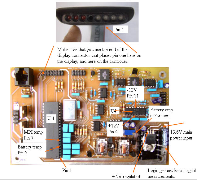
Main Controller test points
|
Test 13.6V supply
Negative probe of your DVM to logic ground. Positive lead to + lead of input filter cap. Should be~ 13.6 with the car running.
|
Test 5V
Connect the negative probe of your DVM to the negative lead of the Input power filter capacitor, or Logic ground. The positive lead will be connected to the left most lead of the regulator IC. Turn on the ignition, but it is not necessary to start the car. The regulated 5V should be 5V +- .2V.
|
+ - 12V supply test
I will be asking you to test voltages on IC pins next. You need sharply pointed test probes to do this, as you must pierce the varnish that is coating the board and components. If your test lead slides off the pin, and shorts two pins, the IC could be damaged, so don't try to do this if you have shaky hands.
First measure the -12V on pin 11 of U4. It should measure -12V +- .2V. Then measure the +12V on U4 pin 4, it should measure +12V +- .2V.
If everything checks out to here, start the car.
|
Board operational check
The car should start just as it did with the test connector, with no IMA or other trouble indicator lights, and should work properly. MIMA cannot operate yet as the MIMA disable switch has not been plugged in.
If you cannot start, start and have a trouble code, and a reset will not fix it, turn off the car, and go to the ECM area first. carefully examine the wires and see if any of the rear T connections have pulled out, or the flying Male to Female junction. This is like an open wire to the computers, and the car will not work.
If the ECM wired are all plugged in properly, carefully redress the wires and tape the whole thing as a bundle to assure that the pins cannot pull out. I also would recommend taping each of the flying leads, but leaving the clear center so you can see if properly connected.
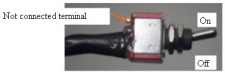
If no IMA or Check engine lights, and power supplies look good to this point, turn off the car, and connect the disable switch, making sure the switch is turned on.
|
Mounting the MIMA disable switch
|  | | | mounting switch and routing wires |
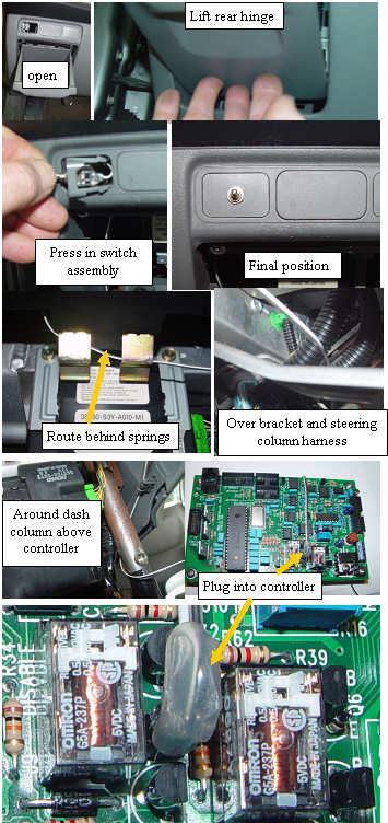
The Insight has three knock out inserts above the small pull out storage compartment (coin pocket) on the lower left of the dash.
Use a small flat blade screwdriver to pry out one of the inserts. The wire must be routed behind the metal spring clips that hold the door open, and over the brace and steering wheel harness(to keep it up and off your feet). The final attachment is a single twist around the center console upright column, and maybe a bit of black tape to hold it. Finally we plug it into the MIMA controller, and are ready to really do MIMA. |
Mounting switch to the pop out panel
|  | | | Mounting the switch in the knockout panel. |
The switch is sized to fit in the smallest of the cutouts. The 1/4" hole needs to be centered pretty well if the switch is to fit between the two mounting tabs. It is a good idea to center punch the middle, or use a small center drill. Assemble the switch with one nut, and the star lockwasher on the inside. Hold the stitch straight while snugging up the nut. This only needs to be tight enough to prevent rotation. |
Installation and introduction: |