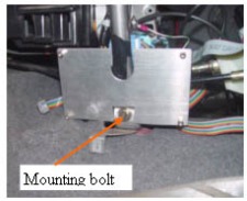
6. Mounting the MIMA system in the car.The mounting bracket for MIMA is mounted to the left pillar on the front of the shift console using the bolt that is already there. The board must be removed from the bracket prior to mounting the bracket.
The upright steel tube will protrude through the notch in the bracket. Before mounting the bracket, stick some black tape on the tube to prevent shorting of the board to the tube.
Loosen the bolt, slide the bracket behind the bolt head and the washer, and down as far as possible, then tighten the bolt. Remount the card to the bracket. Do not connect the Main connector or the Power /fan connector at this time.
|
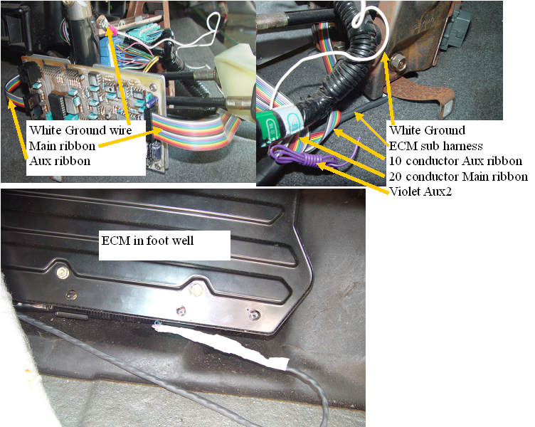
Front end of harness
The front of the harness has several breakouts, the large 20 conductor ribbon connector, is the main MIMA controller I/O. It will feed across to the left side of the shift console, and will later plug into the MIMA card.
The 10 conductor ribbon is the AUX output. This port controls the fans, the FAS, and has one undefined output (Violet wire).
The White ground wire is to be connected to the metal chassis of the car.
Finally the ECM connections need to be fished under the rug to the ECM area. |
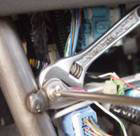
Connecting the white ground wire.
The fan and auxiliary power control outputs use the car chassis as the power ground, and therefore the white wire with the ring terminal coming out of the harness in the shift console must be connected. Using the provided 10-32 screw and nut, attach the ground wire to the hole in the front support arm as shown. Make it tight. |
Installation and introduction: |