|
12. Mounting the low profile display | 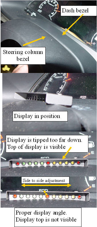 | | | positioning the low profile disply |
The mounting of the new low profile display is very simple. The display is designed to be pressed into the gap between the steering column bezel and the dash bezel.
The problem that had to be overcome was that every car has a different width gap, and some have a rather large mismatch in height between the two bezels. The display angle should be adjusted so the top is invisible to your normal viewing height. The display should also be positioned side to side so that the central led is directly under the C in the FCD lettering under the bargraph.
|
Getting the display wiring routed
|  | | | routing wires and fiting the display |
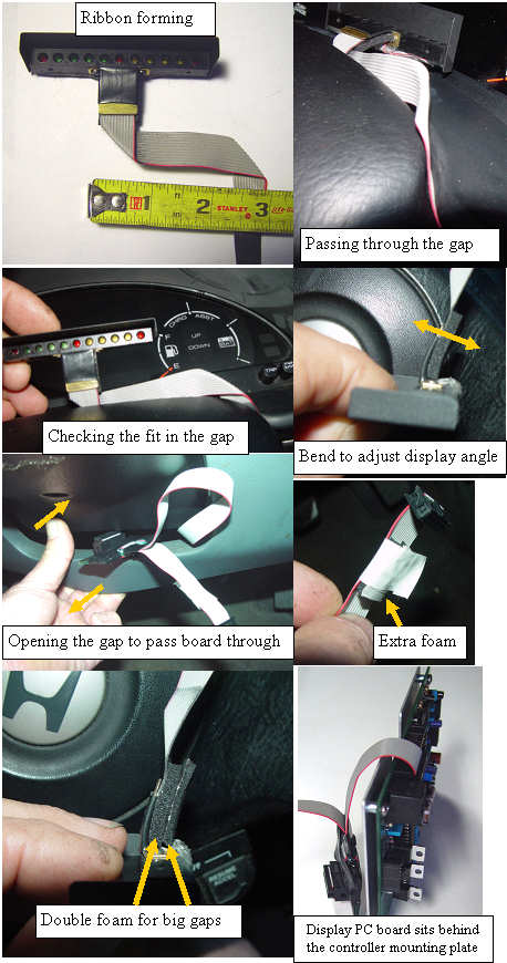
The brass tab that the wires are attached to has a single piece of sticky back foam attached to it. This tab can be bent to adjust the display angle for your viewing height. The display comes with two additional foam strips. If the gap on your car is large, the additional foam can be stuck to the existing foam to make a tighter fit so the display stays in position.
The ribbon cable will need to be bent as shown in the photo, to translate the ribbon to the right side of the steering column. The ribbon must be passed through the bezel's gap on the right side, then it will follow the gap down the right side of the column. The display PC board will next need to be fed through the gap directly under the steering column. This dash bezel can be bent outwards to open the gap so the board can be passed through. The small display PC card will sit behind the aluminum controller mounting bracket, and will plug into the controller display port. |
Installation and introduction: |
|
