Insight 20 AH lithium battery system | 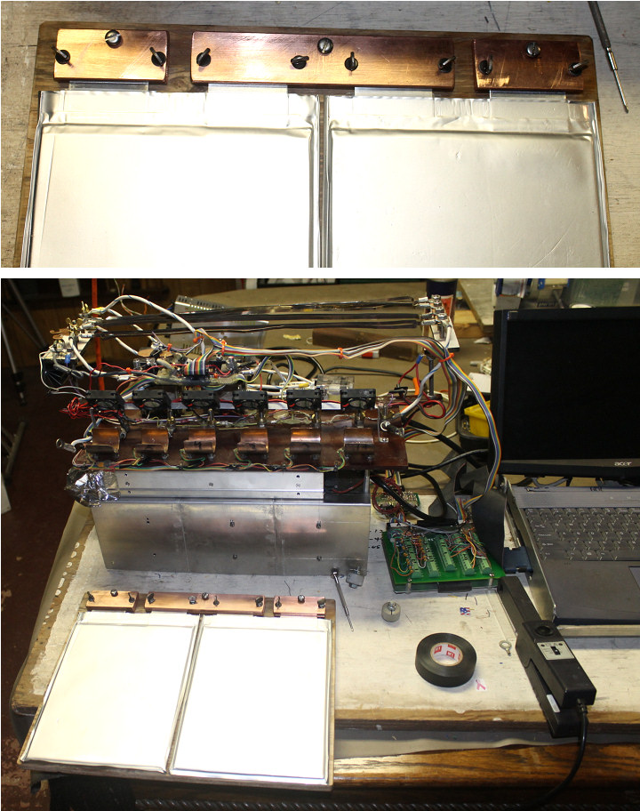 | | | Test fixture takes shape |
The now famous A123 pack is coming back home, guess the guys in Ohio had better things to work on, so the final finishing of the pack is now back on me, but it is now going to be my pack when it is finished.
Will start by designing the BMS I wanted to have.
The blog starts on the bottom of the page.
|
Testing the fans and layout of the BMS boards | 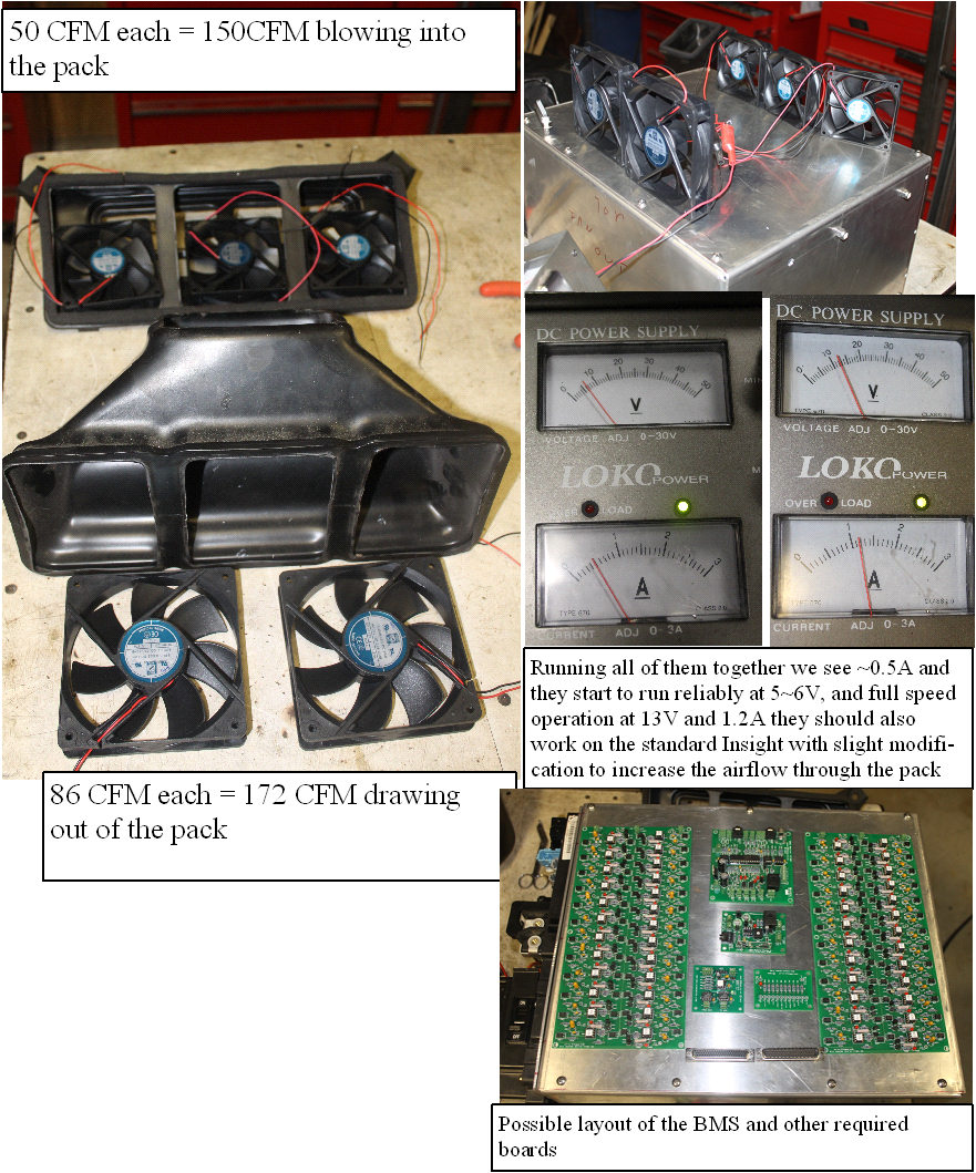 | | | testing the fans 1 |
Got the real fans in today, so I connected all of them to see whay it took to ri=un them, as well as the noise level. The 5 fans were selected for low noise and low current requirements, and sufficient CFM to run a lot of air through the pack.
The max current is 1.2A, and they will run and start reliably at less than 5V, so variable speed should work nicely.
Will mount the two 69 pin connectors to the top, and will drill some air vents both front and rear to draw some air through the BMS area to vent the bypass resistor heat.
(Posted 8/7/2014 by mikey) |
The case is nearly finished | 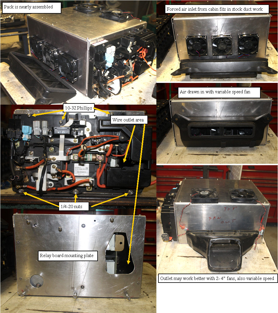 | | | getting it covered up |
Got busy with the aluminum and roughed out the rest of the enclosure. With my simple tools, making a well fitting 1/8" aluminum case is a bit tricky, so there will be some rough corners.I built it to screw together at this point,with the idea that if it needs more rigidity, the screwed together joints could be TIG welded.
The air handling system wants to allow lots of air flow. This gets tricky when you look at the present pack inlet air side where all the air needs to pass through a small louver behind the passenger seat,then take a couple of corners, and pass through the narrow slot where it passes through the IMA box sidewall. Finally it expands out to the full pack inlet.I decided that 3 - 3" fans tucked right in the inlet duct should suck in a much bigger flow of air. On the outlet side, instead of trying to suck out the air with a single fan,I would add 2 more 4" fans directly on the outlet side, and eliminate the fan shroud completely.To control the fan noise, I will build in a temperature controlled PWM fan speed control. The HV connections on the relay board will have big wires attached and will feed into the terminal side of the pack. The cut off relay panel is secured to the pack in exactly the same position as on the stock pack.
(Posted 8/3/2014 by mikey) |
The Battery case starts to take shape | 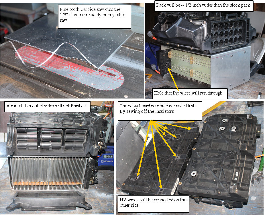 | | | making the battery enclosure |
Finally got the rear shop cleared enough to cut up the aluminum sheets. 1/8" 4X8 sheet is a bear for one guy to handle.
After rigging up some support I was able to cut the sheet in half, and that size can be handled with good control.
After giving up trying to cut the stuff with the jump shear, I found that an 80 tooth carbide blade cuts the sheet easily, so I was good to go.
I cut off the rear protrusions (HV terminal insulators) and the top mounting bosses, as I will be mounting and wiring it differently than it was on a stock pack.
Got my big brake set up so I can make nice bends, so I think I will make the pack so it screws together rather than welding it together. This will allow better access in the event of a problem.
Still need to make the air inlet and outlet sides and then locate and drill the main mounting holes for the pack core into the case, as well as the 4 main mounting bosses
(Posted 6/19/2014 by mikey) |
Capturing the mounting boss positions | 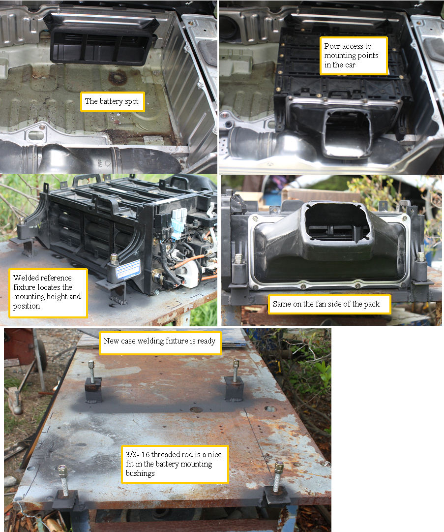 | | | battery case fixture |
To make a drop in pack, we need to accurately have mounting bosses in the exact position as the stock pack. After a careful look at the empty IMA bay on the green Insight. I decided that it would be easier to duplicate the mounting boss position on the new pack, if I had a solid fixture. I used an empty case as a template to hold the angles, and then welded them to the 3/4 inch steel plate.
(Posted 5/21/2014 by mikey) |
BMS board mounting position? | 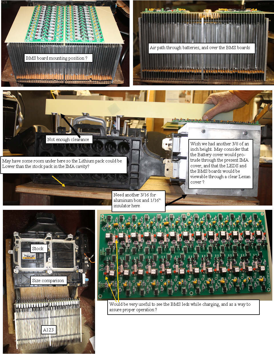 | | | BMS boards mounting |
Now that I have the battery assembly in hand, we can start to look at the mounting options for the BMS boards. We plan on moving the stock BCM and MCM to the area between the seat back and the IMA box.
I can see now that this would have been easier had I made the fins ~ 1/4" shorter,(would require complete disassembly now, so that is not a good option), but the cooling / heating can use all the fin length we have and more, so it was a tough call. The ability to see all the BMS LED while charging will be a nice aid in keeping an eye on how well the pack tops off, so it may be nice to let the BMS part of the pack cover stick through the IMA box cover, and to have clear lexan cover area so the leds and the board are visible?
No need to hide the cool looking "flux capacitor" boards. Could mock up a MR Fusion machine to give it the back to the future look. May be able to find some clearance under the stock pack to gain some height?
Time to look at the IMA cavity closely.
(Posted 5/15/2014 by mikey) |
the connector plate is made and mounted | 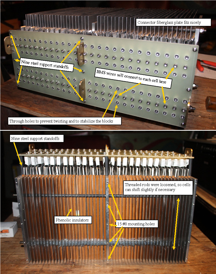 | | | assembling the connector plate |
Probably the most critical part so far, this plate had to tie the pack together,and provide secure connection points for the BMS wires to each cell.
With anything like this where the cells were not uniform, I had to take the 3 dimensional stack of cells with connector blocks, and make an insulating plate that would line up with the connecter blocks and the 9 standoffs. I aproximated the positions of the blocks, and then adjusted the drawing to compensate for as built variations. I finally got the drawing where I wanted it, and machined the plate. I was happy when the plate fit nicely.
I loosened the threaded rods when the connector blocks were secured to allow the cells to shift the tiny amount that was required to get them all at the correct height and position.
Next step is to make the case, which will have to allow mounting of a standard relay assembly.
(Posted 5/9/2014 by mikey) |
Final assembled pack core | 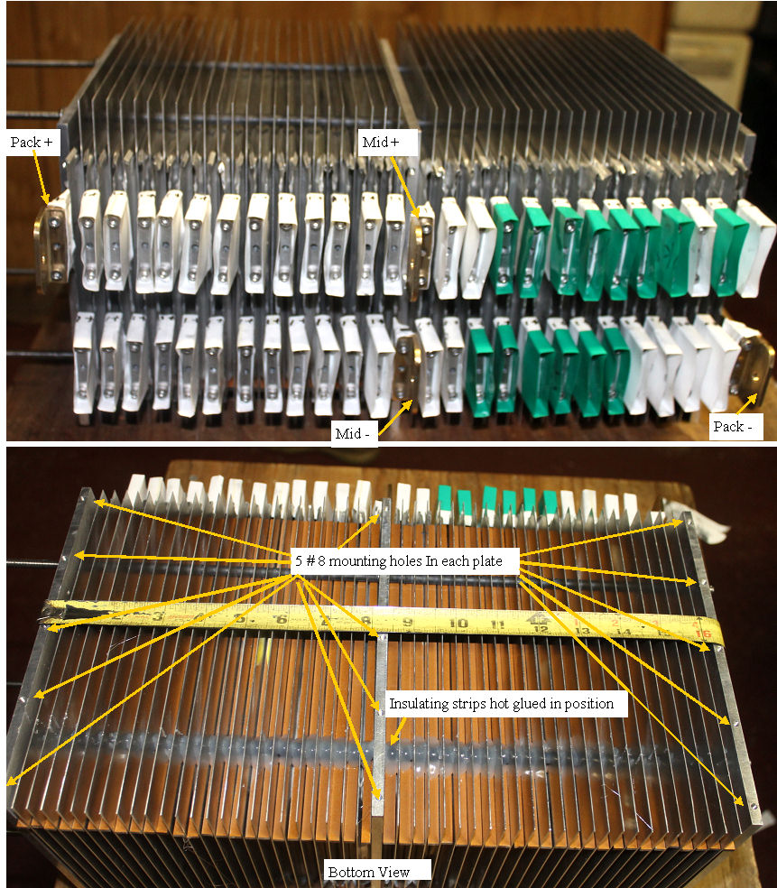 | | | lithium pack core assembly |
The main threaded rod clamps were tightened, and the insulating strips were hot glued in position so they can't slide out. The 3 main plates will be the attachment to the outer pack, and each had 5 # 8 screws, which should make a very secure attachment.
Next I need to make the large Fiberglas mounting plate to secure the connections, and give me a way to connect the BMS wiring.
the pack core is 11.5" wide, 16.5" long, 9" tall have not weighed it yet.
(Posted 3/14/2014 by mikey) |
assembling the pack core | 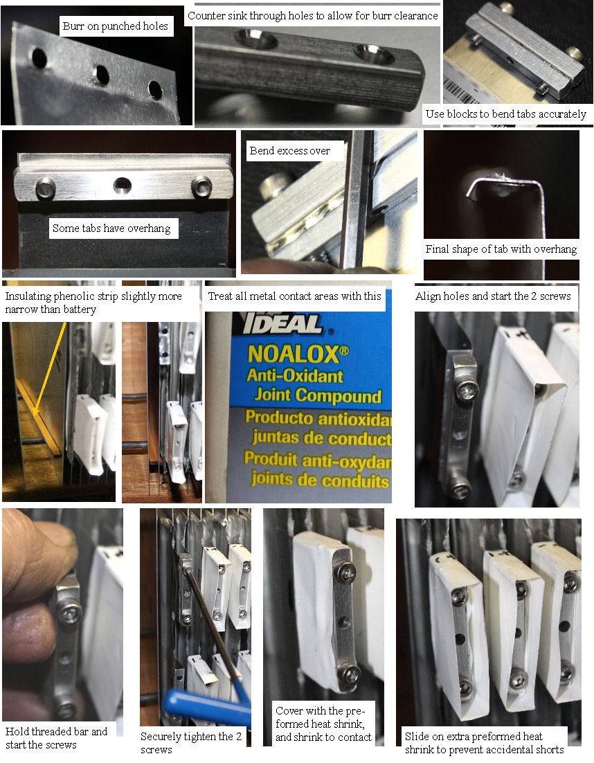 | | | carefully assembling the pack |
Now that I have made all the required parts, it is time to do the final core pack assembly, hopefully with no shorts.
The first issue was the small burr on the punched holes, that would be a very big job to remove. The fear is that the clamps would only apply pressure on the raised burr, and therefore all of the current would pass through the rather small area. The simplest fix was pretty easy, I put a nice counter sink on the clearance blocks, so the burr would be able to fall into the countersink and therefore allow the full area of the blocks to apply pressure. The assembly process proceeds as shown in the photo. The anti oxidation paste is heavily zinc filled, so it should provide corrosion protection while not effecting the contact resistance. The connections were insulated with the preformed heat shrink, and then an additional piece of the preform is slid over the end to prevent shorting. This extra protector will be removed when the contact plate is attached. Each cell took about 10 minutes to prepare and connect. Long day!
(Posted 3/14/2014 by mikey) |
Insulators | 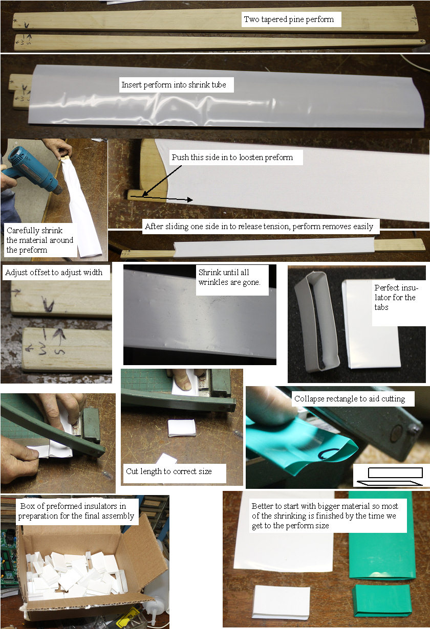 | | | making the insulating preforms |
As shown below, the biggest issue with assembling the pack safely with charged batteries is keeping all the junctions between cells separated until they can be properly supported. The shaped heat shrink seems to do the job, so I made a new inner form out of pine to make a bunch of the insulators.
The remaining shrink had a lot to do with how distorted the rectangular shape got when the final shrink took place. It seems that using a larger shrink tube using most of the shrink to achieve the preform was much better than only shrinking a small amount to achieve the preform, so I used the larger white shrink.
(Posted 2/3/2014 by mikey) |
main I/O terminals and Heat shrink | 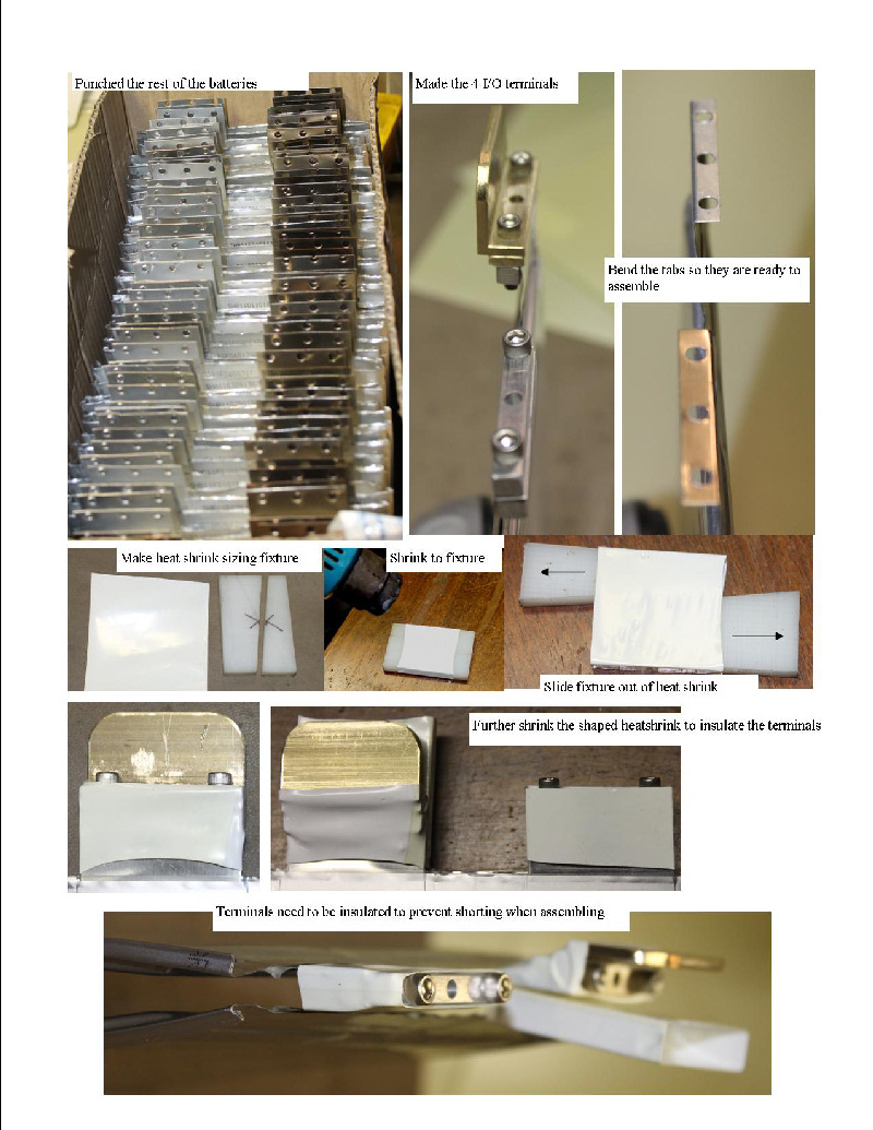 | | | figuring out how to assemble it |
Designed and built the 4 main I/O terminals for the pack, then punched the rest of the tabs.
The final assembly of the pack with charged batteries is very tricky, and I need to carefully consider the best way to do it. the batteries can put out hundreds of amps, so a short even between adjacent batteries is going to be very bad, so I make a shaping fixture that pre-sizes the large heat shrink I have so it nicely fits over the interconnect blocks. Hopefully this will prevent any possibility of them shorting.
Will need to tweak the process as I proceed.
(Posted 11/20/2013 by mikey) |
Punching the holes in the tabs | 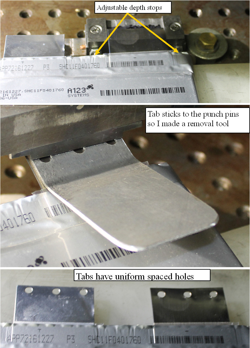 | | | punching the connection holes in the tabs |
Set up an insulated table for the cell body, and insulated the parts of the punch that could short the hot battery terminals. Adjusted the two stops to assure reasonably uniform position for the row of holes.The punch sticks on the punch pins so I had to make a tool to easily release the tab with no distortion.
(Posted 11/5/2013 by mikey) |
Cleaning the cell tabs | 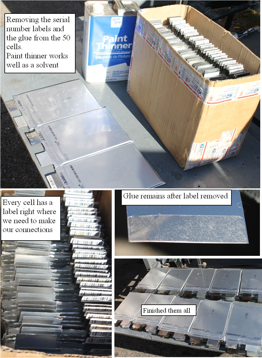 | | | cleaning the cell tabs |
Each cell has a serial number label on the - tab, and even when the tag is removed, the adhesive remains on the tab. Paint thinner is a good solvent for the adhesive, so I used a saturated rag and cleaned all the tabs.There goes 4 more hours. Turning into a lot of mechanical work, and I have not even started the case.
(Posted 11/5/2013 by mikey) |
fixing and deburring the heat spreaders | 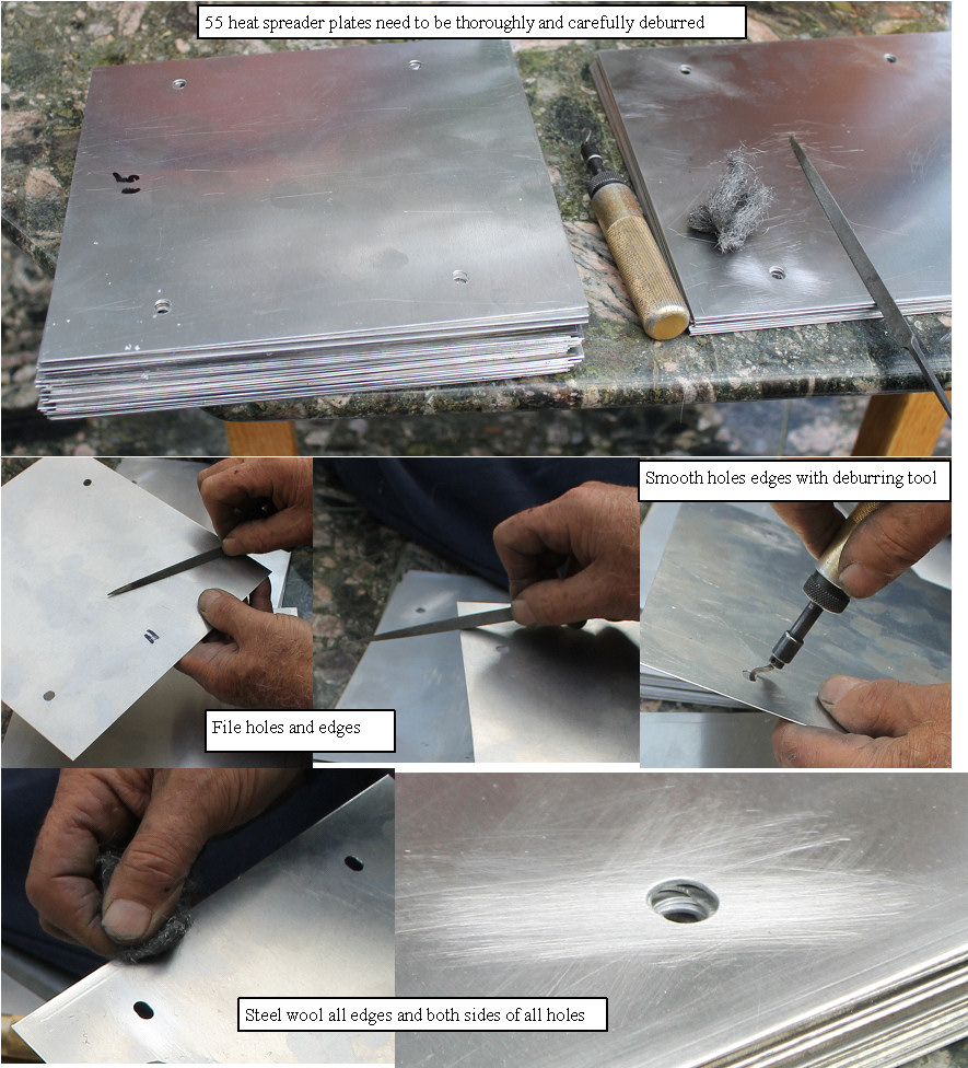 | | | cleaning up the heat spreaders |
When I went to do a dry assembly of the heat spreaders, I saw that the drill had wandered by as much as 1/8"when I drilled all of them together with the 1/4" plates. This will cause issues later so I took each plate and milled a corrected hole in the exact correct position, which ment 55 X 4 more operations, there goes another part of a day.
Once finished, the plates need to be cleaned up.
Decided that if the aluminum heat spreader plates were very thoroughly deburred, that there should be no issues with a cell/heatspreader/cell/heatspreader sandwich construction, so I spent the better part of a day cleaning up and deburring the plates.
(Posted 11/5/2013 by mikey) |
Making the 50 insulating strips | 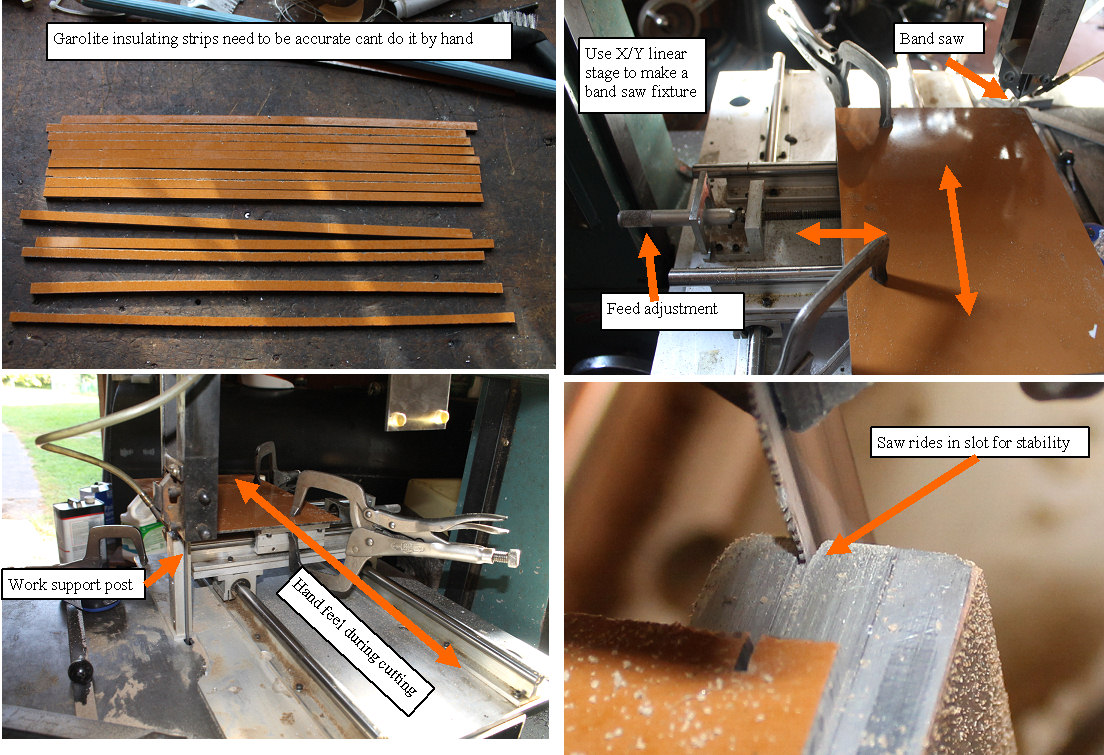 | | | accurate cutting fixture |
Got some 1/8" phenolic material for the insulating strips. and tred to cut them accurately to 1/4" strips, but it was very difficult to get them straight by simply using a side guide. I dug out an X/Y scan table that I modified to make an accurate cutting fixture. Works quite well, and the strips are all made. Another piece of the puzzle.
(Posted 9/21/2013 by mikey) |
finishing the fins and end plates | 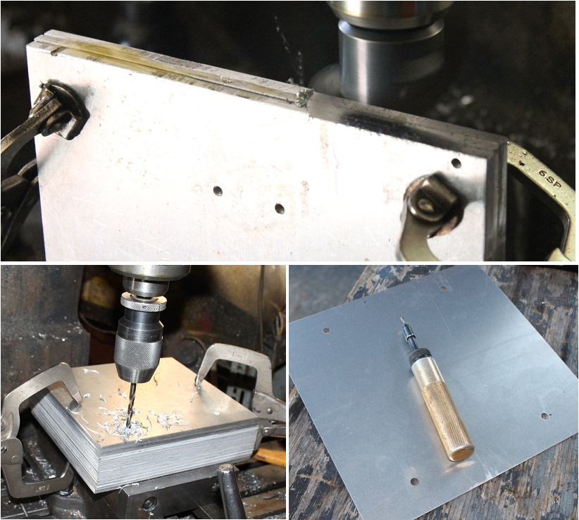 | | | finishing the plates and fins |
made the three 1/4" plates, and drilled holes in all the fins. removed the sharp edges of all parts.
******* the plates slipped a bit which made the holes not be in the correct position, which took a lot of work to correct. Best clamp the plates tightly, or better yet drill each plate individually**********
(Posted 9/19/2013 by mikey) |
Heat sink fins | 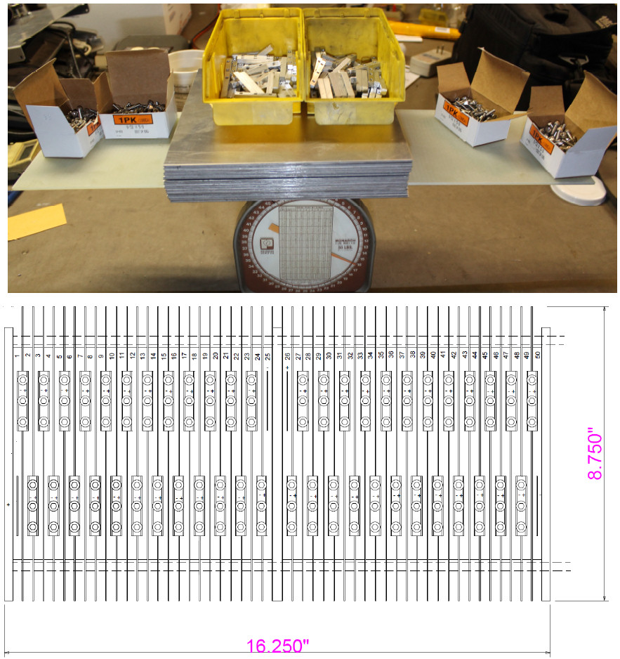 | | | getting started with the heat sink plates |
Took a ride to my local metal supplier and got a full 4X8' sheet of 0.032 aluminum, and cut it up into 55 plates. put the plates the screws, the G10 insulator and the bars on a scale to get a rough idea as to the weight. Looks like ~ 16 lbs so far. will still need 3 1/4" plates for the ends and middle,the threaded ros and nuts, and the wiring and BMS boards and the enclosure. The bottom drawing shows the way I intend to stack and connect the cells
(Posted 9/17/2013 by mikey) |
The tab punch | 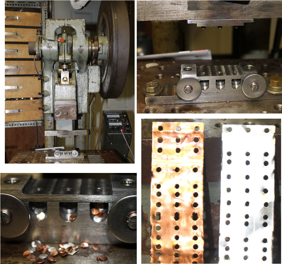 | | | Punch for putting holes in the cell tabs |
Made the punch and die for the tab punch.
It has an adjustable hole position stop, and can punch the copper and aluminum tabs consistently.
I modified the dies used to make the MIMA display bezel, but it still took most of the day. Have some fiberglas and special bolts coming tomorrow.
(Posted 9/16/2013 by mikey) |
Finishing the connection blocks | 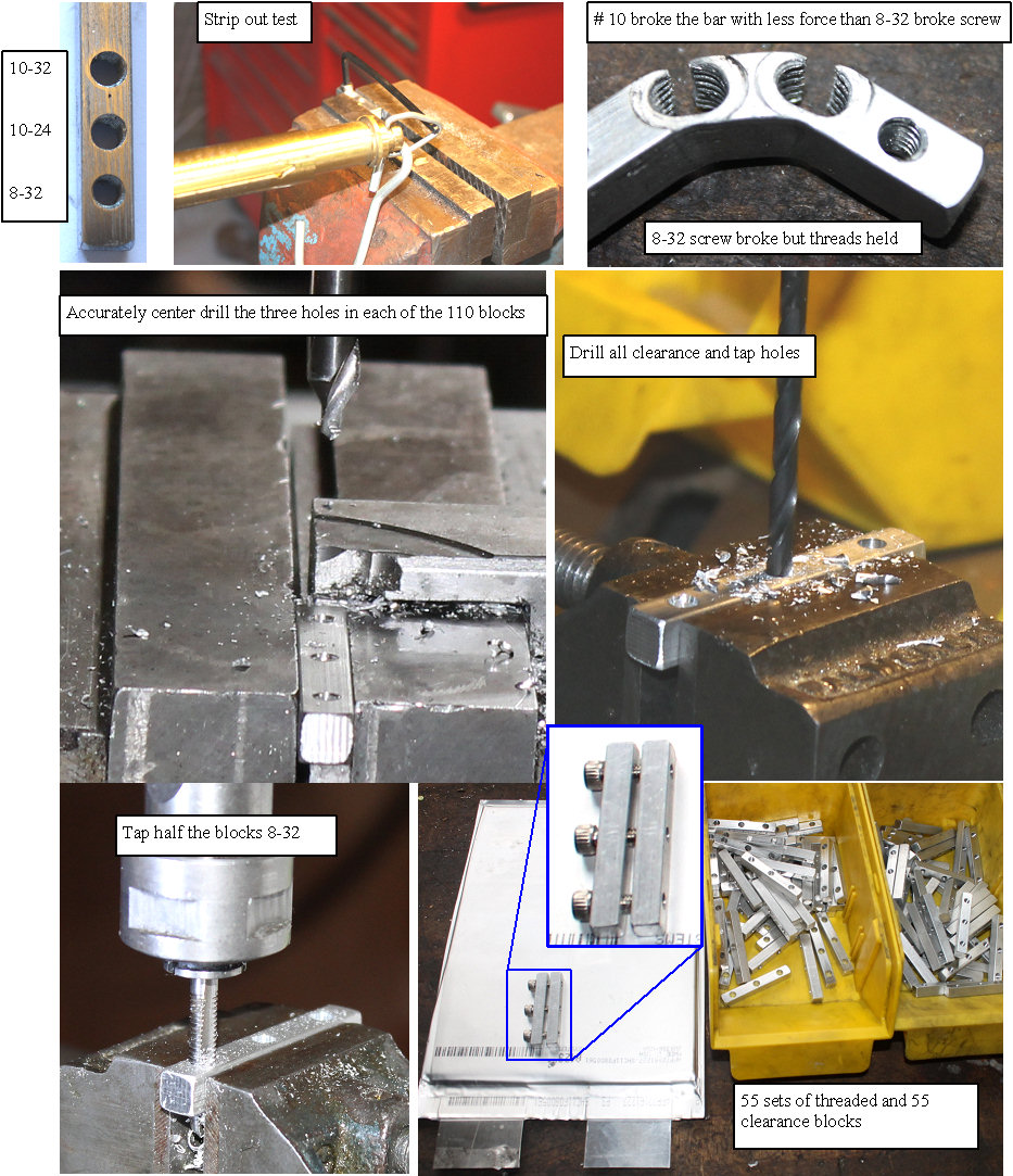 | | | lots of drilling and tapping but now they are finished |
Spent most of Saturday drilling tapping deburring, and cleaning the 110 blocks.
To determine the best screw, I drilled and tapped an 8-32, 10-32, and 10-24 threaded holes in the bar, and with scale recording the force to break the screw or strip it out, the best candidate looks like the 8-32, so that was the size holes and tap I used.
(Posted 9/14/2013 by mikey) |
Getting started on the final design and build | 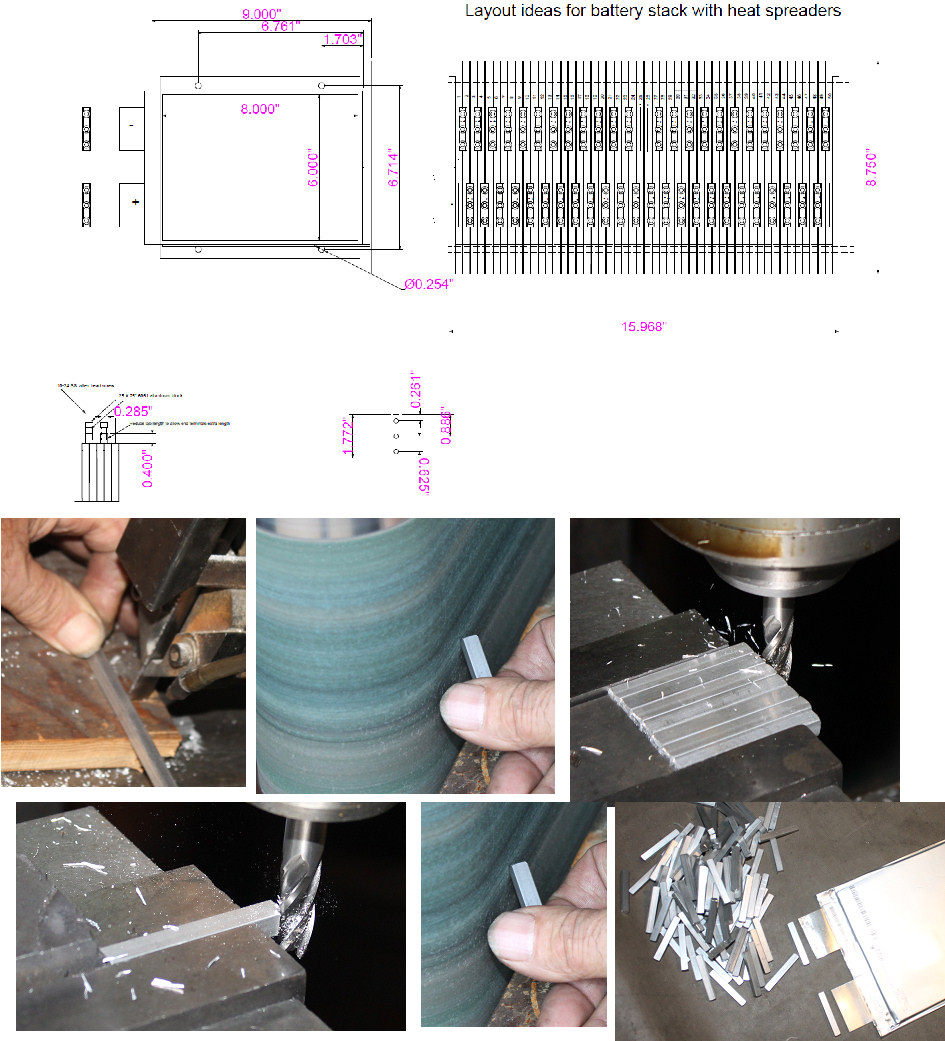 | | | making the buss bars |
After looking over all the data and lots of other peoples approach to using the A123 batteries, I still think my original cell to cell and voltage tap concept is going to be the way I will go. If a cell fails, I want to be able to fix it, and since the pack will have a smart BMS, it will tell me which cell is bad, so I may as well put in the work up front to retain that possibility.
Started by rough cutting the 1/4"X 1/4"aluminum 6061 T6 bars to a bit longer than we need with the bandsaw.
Then in order to remove the burrs, I ran all of them through a deburring step on the belt sander.
Next I milled all of them on one side, still longer than the final length desired.
Turned them all around, and made the second side exactly the final length required.
A final deburing with belt sander, and the 110 blocks are ready to drill and tap the holes.
Next task is the cell tab punch, and a final determination as to the best screw size to use for the clamping.
(Posted 9/13/2013 by mikey) |
How do the big guys do it | 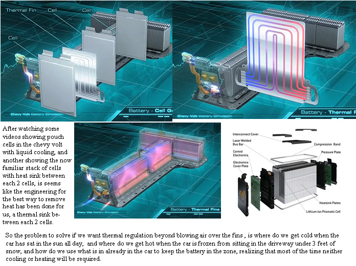 | | | How do the big guys do it? |
After the initial experiments,and getting a better feel for the characteristics of these cells, I did some searching for how these type cells are cooled in real world applications. Both of the pictured automotive systems have liquid cooling of the pack. A commercial vehicle that can be sold in the 50 states needs to operate over some big extremes in environment. The guys that have seen their Insight or Civic start on the 12V starter in winter ,can also be the ones that could get the inside of the car to 120F in a parking lot in summer, so to design a pack, one needs to decide if they are willing to risk battery damage at the extremes, or do we want to provide active cooling heating into the system.
So lets throw out some ideas:
The AC can generate cold, and the heater can generate hot, so an air fluid heat exchanger right in the AC/heater ducting with separate insulated fluid handling system to a heat exchanger along the sides of the pack as in the bottom photo, or possibly a ducted path for the heater / AC output to the pack blowing over the extended fins of the thermal spacers.
The two cells/ heat exchanger plate probably works fine when you can send chilled fluid through a heatsink on the plates or through the plate it self like the volt.
For an air cooled system, a plate between each cell would provide the best solution. The problem comes when you have a car at 120F and everything in it including the air and battery is at the same temperature. The opposite when the car and batteries are frozen at 10 below zero.
In a garage, AC power could keep the pack in the zone, but then you are in trouble if the car is not home and you need to overnight in cold climates.
The cells are rated to operate to -22, but based on the changes I see at 40F, I would not expect much performance in below zero temperatures, and to wait for the car to warm up and then the warm air to heat the pack, and you may be at your destination before your in the best temperature zone?
(Posted 6/29/2012 by mikey) |
Hot and cold cells compared. | 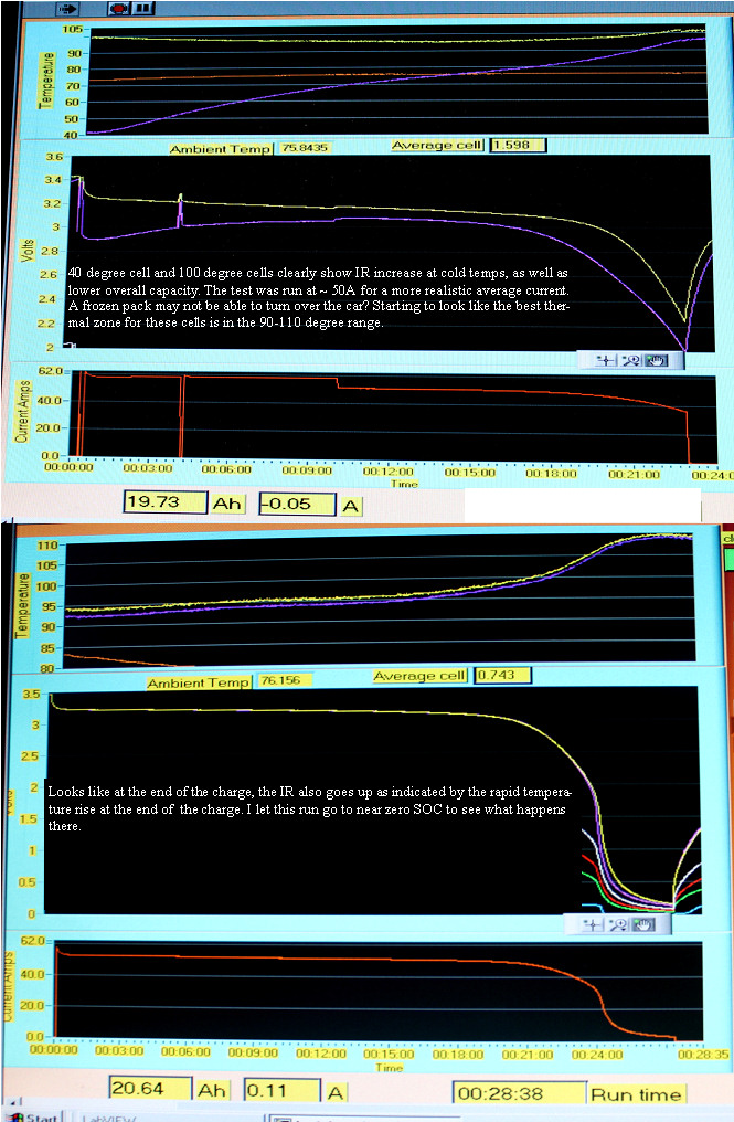 | | | hot and cold cells compared |
I charged both cells, then put one in the sun, and one in the freezer, and then once the temperatures stabilized, as quickly as I could, placed them in the test fixture and ran a medium 50A discharge to see what happened. The cold cell had a much bigger voltage drop that got better as the cell self heated, and the hot cell actually dropped in temperature before turning around and rising towards the end.
Looks like the cells like between 90-110F as their best performance zone.
Ran another run where I let the cells drop right out, and we see evidence that the self heating gets worse as the cells start dropping that last 2V.
(Posted 6/29/2012 by mikey) |
Higher thermal sensitivity look at the cell heating still shows no dents | 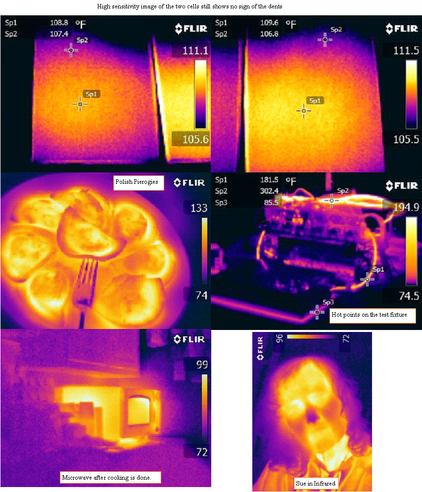 | | | A better look at the cells for effects of the dents |
The thermal images are in a special JPEG format that stores the ratiometric thermal data for each pixel, so reprocessing the image with different thermal scales and ranges is possible.
I reduced the thermal range represented by the color scale to show any thermal gradients across the cells, and still no sign of the dents, so I don't think it effects the cell performance at least in the limited samples I have.
The images is really 19,200 individual IR thermometers, so there is a lot of data there.
The test fixture photo with a few more thermal points
My dinner of some Polish Pierogies, the hot microwave, and a scary picture of the wife.
(Posted 6/27/2012 by mikey) |
Painted cells to increase emissivity | 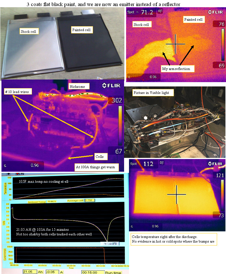 | | | > 100A discharge yields 21AH |
Put 3 coats of flat black paint on the cells to make the cell surface more of an emitter, so I can get some good thermal uniformity photos.
The discharge was at the highest so far at 103A, and as the photos show. we had some red glowing load bands. Even the #10 lead wires got up to over 100F.
The cells did even better at the 103A than they did at 68A, so I suspect that warm is better than cool for getting the most energy out out of the cells.
Next test will be to freeze the fixture and see what the differences may be.
Pretty impressive cells for sure.
(Posted 6/27/2012 by mikey) |
The world in IR Cool | 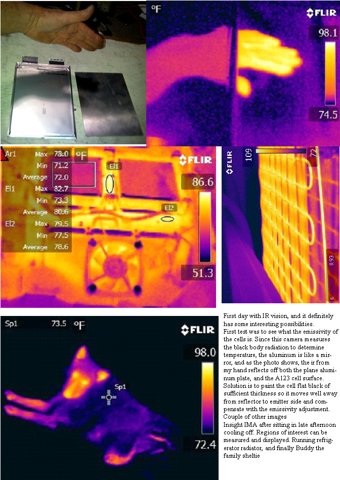 | | | Some new eyes take a look at the thermal world |
My new instrument arrived today, and the 4 hours I had to wait for th battery to charge before turning it on were like hell.
Finally the first look, and 2 hours later I finally pointed it at the A123 cell. The biggest factor in accuracy with IR imagers is the emissivity of the surface. Aluminum, Copper shiny steel and most metals are more reflective than emitting, but only a thin layer of rust, anodizing or paint is required to make the surface emit the correct black body radiation.
So I will paint the cells until the reflection is minimized, and run some more thermal test to see if the dents in the cells are a different temperature than the areas not stretched.
(Posted 6/26/2012 by mikey) |
heatsink vs no heatsink comparison | 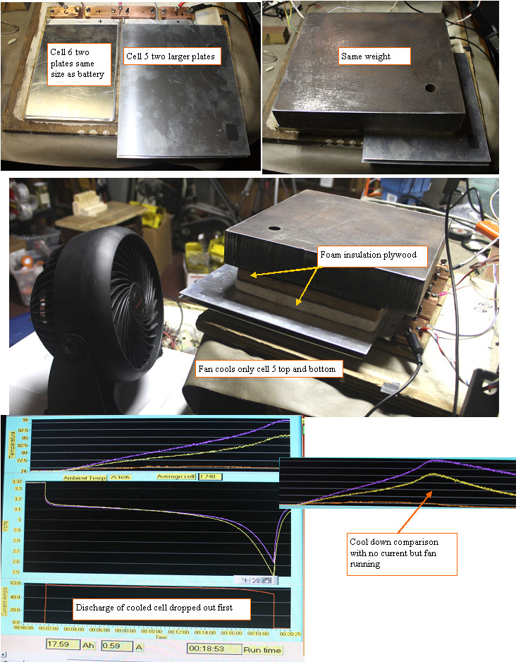 | | | A-B comparison of cell with heatsink and cell without |
I set up an interesting thermal comparison. I made two 0.061" thick aluminum plates that are the same size as the cells, and two that were 2" longer and wider.
I placed the same size plates top and bottom of one cell. and the larger plates so the extra 2"of plate was off the bottom and one side of the other cell. the top and bottom plates form a heat sink area where I can blow air.
As expected, the cell with extra fins was only half as hot as the one with only the plates, it stayed under 85F. What I did not expect was that the cool cell dropped off noticeably quicker than the warm one. will reverse the heatsinks and do another run, to see if things change cells as final confirmation.
**** Results of moving the heat sink to the other cell was as expected, the cool side being changed also changed the cell that dropped out first almost exactly the mirror image of this trace. Temperature matters. Where is the sweet spot between longevity, temperature, capacity
(Posted 6/25/2012 by mikey) |
Same discharge with huge heat sink on one side of cell | 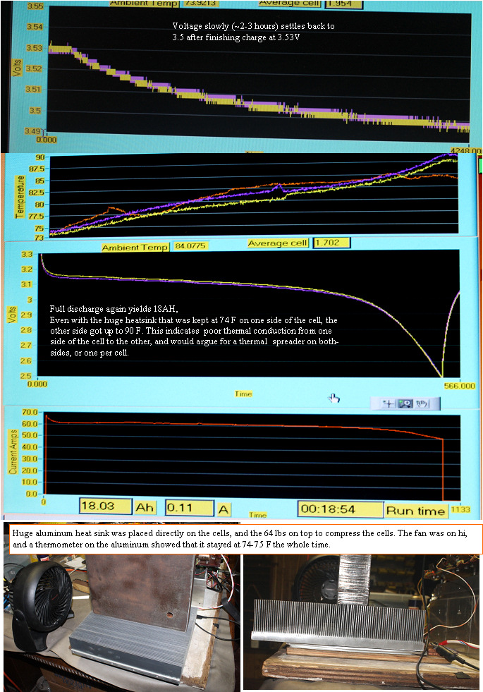 | | | even a monster heat sink cant get the heat out from one side |
We saw 100F at the end of the first 62A discharge on the cells with no heatsink. I did the same 62A discharge, but this time instead of insulation, I used a huge finned aluminum heat sink,with a lot of air running over it. the idea is to see how well the heat generated in the discharge was transferred out of the cell with one side kept at 74F.
I was a bit disappointed to see the temp on the back side was only held to 90 degrees instead of the 100. This would lead me to believe that the heat sinks would work much better if they were on both sides of each cell rather than every other one?
Opinions?
Note*
The ambient temperature probe was getting heated by the discharge load. will move it to a better spot in the next test
(Posted 6/24/2012 by mikey) |
Charging experiments | 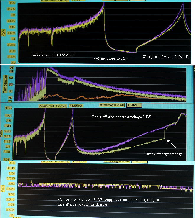 | | | high medium and low charge rates compared |
In preparation for the second discharge I tried charging three different ways.
First I charged at 34A till the first cell hit 3.55V
On turning off the charge, the voltage immediately dropped to only slightly more than the starting voltage.
I next charged again at ~7A, and the pack voltage again rose to the 3.55 and dropped out, only to show the voltage again drop to a lower value, but higher than the first rebound.
Finally I set up two constant voltage supplies for 3.53V, and let the charger stay connected until the current drops to near zero.
After removing the charger, the voltage stayed at the 3.53V
Hi current charge gets you to the target fast, but then you have to hold the target voltage until the current drops to few ma as the cell fully charges.
Probably better to approach it more slowley, at a more moderate rate.5-8A may be a nice number.
(Posted 6/24/2012 by mikey) |
First discharge graph | 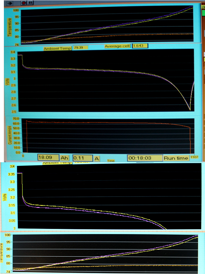 | | | First recorded discharge, first test ot test fixture |
Well the fixture seems to work. I think that we have a test system.
Some uncertainty as to if I was fully charged at the start, but we have a respectable 18AH
The temperature rose immediately and this was at only 68A, so I want some active cooling, based on just this test.
Next I will charge back up, and re-run the test but this time with an infinite heat sink right against the cells instead of the insulation.
The violet cell started at a lower voltage, but soon after the discharge started it was higher, and it remained higher for the rest of the discharge.
Wonder what that means?
(Posted 6/23/2012 by mikey) |
Cell tester is modified and lithium test fixture takes shape. | 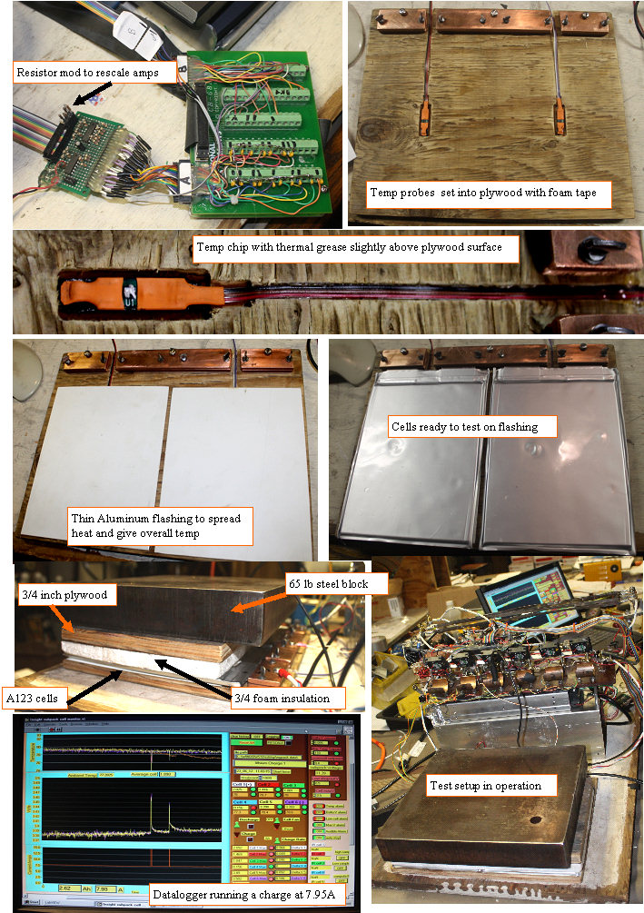 | | | Getting set up for some testing |
Got out the soldering iron, and made some modifications to the cell tester. Had to disable the other 4 cell channels,and have special calibration valuse for the lithium cells in the software.
Added max V charge stop in the test software.
had to add a header on the cel voltage amp where I can plug in some gain changing resistors, to rescale the amplifiers.
Set uo two temperature boards dead center on each cell, and mounted the board on some soft foam mounting tape, so it sits just a bit above the surface of the plywood, made two thin aluminum flashing rectangles for the cells to sit on, so the whole cell temp is better represented by the single temp probe. The cells need pressure on them to assure intimate contact between the plates and the electrolyte saturated spacers, and since the purpose of the test is to see the thermal characteristics of the cell, I opted to use a 3/4" foam/3/4" plywood pressure plate, with a 65 lb block of steel as a weight. This should allow us to first test the non cooled cell, and to clearly see any heating effect, as the aluminum plate will show the overall cell back side temperature. Once we see how the cells behave at 100A, and see any heating, we can try different cooling plate thicknesses on the top side and hopefully see the effect of active cooling in the bottom thermal monitoring zone, which should simulate the cell to cell juncture in a 2 cell stack.
At high charge currents, I see some temperature measurement errors, so I need to do a bit more work on the amplifiers.
In all it is already quite useful, and hopefully I can get us a discharge graph and AH measurement soon.
(Posted 6/23/2012 by mikey) |
Is using this asking for a problem? | 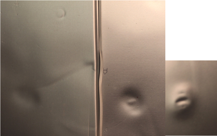 | | | Is this going to be a problem? |
In the 56 cell batch of pouches, two of the cells showed evidence of getting hit with an object that dented them right through. I will use the two dented cells for the first test, and see if his area gets hotter, or if the cell is degraded in any measurable way, but common sense would make one not want to bury this in a pack of nice flat cells.
(Posted 6/21/2012 by mikey) |
|
