Pack discharger | 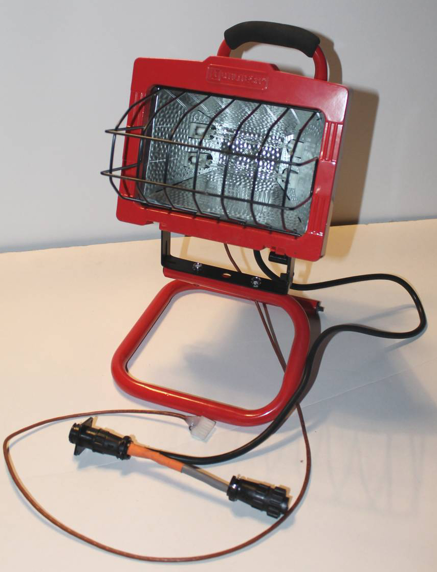 | | | final discharger accessory for charger |
*************************************************
Notice
I had a guy in Arizona stick the discharger in a closed hatch at >100F, and when the discharge ended, the discharger stayed on, and the charger started charging, the discharge is 2A, the charger is only 1A, so the pack saw a 1A discharge, and the only way to stop it was to turn off the pack, or unplug the discharger from the car harness while current was flowing. Not a good thing.
The Power mosfet failed shorted due to overheating.
A shorted mosfet is out of control of the charger, so it would have totally discharged the pack had he not been checking it when it started charging.
We can't stop the discharger if the mosfet won't shut off, but we can make the charger make some very noticeable noises to get your attention, and we can advise that all cycling is done in a car that is well ventilated, and below 100 degrees., preferabally much lower than that.
We will have new code hopefully early next week, that we will install in all the new batch of chargers.
This code detects the shorted discharger and makes a lot of noise to let you know.
It also gives full discharge control to the user when they are in the password protected tech edit Discharger stop bypass mode.
This was an extreme temperature condition, and under normal temperatures, the heat sink is hardly warm.
The Max load current is 2A, the mosfet is rated for 8A, so we are well into the conservative area, and should not have thermal problems unless the ambient is too high.
I Also advise that the rug and IMA switch cover is exposed so the main breaker can be turned off to end a shorted discharge safely. Pulling the charge connector may arc and damage the connector pin.
Glad we heard about this before I shipped a bunch of the chargers.
For the people that already have upgraded code, and a discharger, contact me and we will get your chip upgraded, just ask that you send the old one back.
Discharger assembly and test video
So be careful, Best leave the discharging for the moderate temperatures below 90F
*****************************************************
The charger can do a much better job of balancing a battery if the pack can be discharged deeply, but not so deep that any cells reverse.
The Dis-charger accessory for the grid charger can do that function.
The discharger is pretty simple, just an optically isolated 250V Power MOSFET that acts as a computer controlled HV switch to connect and disconnect the discharger to the pack.
The schematic for the basic circuit is here:
Discharger rev 2 shoplight
Another function that can be performed with the charger and discharger is subpack internal resistance comparisons.
Every battery has a characteristic called Internal resistance (IR). This is a very important number, as it will determine how well the cell can output current. A cell with high IR will drop in voltage much more than a cell with low IR when under a load,and will heat up much more as well.
The same cell and will rise in voltage when charged more than a low IR cell.
The actual voltage drop with knowledge of the current flowing can give us the IR, which for NIMH batteries, can be a pretty small value.
So how do we reliably measure this small value with the charger/discharger?
The difficulty in measuring IR's small voltage, is that the voltage is riding on the 7-8V DC that the subpack is at, so the meters ability to see voltage of as little as 0.002V when on a scale that can read 8V requires a special differential meter. A second problem is that as the load is draining current from the pack, the overall voltage is also dropping as the SOC drops, so you have a moving target.
The discharger and charger have a pulse mode.
This mode is protected by the tech edit password, as it must be used correctly or over discharging of the pack can occur.Since we are trying to compare the IR of all the sticks to determine if any are high in IR, the pack would be disassembled on the bench to allow access to the end points of the sticks.
The pulse mode turns the discharger on, and then off at 33HZ, so effectively current is flowing for half the time, and not for the other half. The frequency is nearly 50HZ, so it falls in the range of the regular 50-60HX AC line.
The test mode is turned on, and while the pack is slowly discharging.
Since the series string of cells is all being pulsed at the same time, the same current will be drawn on all cells, so all cells have the same pulsing current.
The AC meter setting will block the DC of the cell, and only show the AC voltage produced when the current goes on and off, and the stick voltage varies at 48HZ. The voltages are still small, but most DVMs can easily and reliably read the AC value.
Run quickly down the string of subpacks, and record the voltages, and if any subpack has a noticeably higher AC voltage, it will likely be the one causing your problems. The resistance of the harness, Harness fuse, main contactor, and main 100A fuse are all adding to the total pack IR, so the best place to get a true pack IR is right at the charger tie in points, but be aware that the main fuse, main switch, and all the internal bus bars are being included in the test.
On the subpack level test, we are right on the subpack terminals, so the IR value will be quite accurate. I will be doing a whole series of You tube videos on how to use the charger and how to do this test, and how to interpret the results.
A graph of one of the subpacks that was pulsed with a 30A charge, clearly shows that the blue trace (cell4) has a much higher IR than the rest of the cells in the stick.
Cell #4 with High IR
Discharger current at different voltages
170V = 1.701A
158 = 1.689A
150 = 1.643A
140 = 1.580A
125 = 1.482A
120 = 1.450A
119 = 1.382A
100 = 1.309A
90 = 1.23A
80 = 1.162A
70 = 1.087A
60 = .997A
50 = .910A
**************************************************
Be aware that until you have Charger code V2.0, or higher the discharger will not work.
**************************************************
The cost are:
Shoplight $24
HV Mosfet $9
Aluminum heatsink/box cover, materials and labor $ 20
Extension harness with HV tap attached to shop light cord $50
Aux control cable, with Aux connector attached $7
Labor to rewire shop light and attach cables $25
Total $135, plus actual shipping.
Shipping:
Zone 8 --$37, Zone 7 --$32, Zone 6 --$29, Zone 5 --$26, Zone 4 --
$20, Zone 3 --$17, Zone 1-2 --$15
The discharger will come with the required in charger connector.
A special 8" Aux harness with 3 foot cable for tie in to your DIY discharger would be $50
Contact me directly if you are interested.
contact us
FAQ
My charger is working great. Now, I've been following your work on the discharger and am trying to determine whether I really need one. I stumbled across this a post of yours from back in July of 2011:
thread
In this post you state:
"A smart discharger/cycler/tester, for deeper diagnostics of a pack that is not able to be brought back with the charging/balancing." This sentence gives me the impression that the discharger is perhaps not necessary for everybody and that the charger, alone, may be sufficient for some.
As I'm sure you can understand, I'm just trying to control my spending if I don't really need the discharger. For somebody who isn't very knowledgeable in battery chemistry, can you help me understand how I can determine if I can skip the discharger?
When I wrote that, I was expecting that we would have no problem doing a good discharge by driving, but that seems to be more difficult than I anticipated.
From my experiments here, the charging balances all cells at 100% SOC, but it looks like unless we discharge the pack to as low a point as possible, the cells capacity will not recover as well as it could. When discharging with driving, we are both discharging and charging, and the car fights us when we try to deplete the pack, and finally the pack will never fully discharge below 20%.
This cycling from full to empty is the basis of many RC battery chargers/conditioners, and is the main technique that is being used by battery rebuilders, as the first step in rejuvenating an unbalanced pack.
The silver Insight that has been sitting for 2.5 years in my driveway, has an old pack that sat idle except for maybe 4 charges over that period.
I pulled it out as a test pack for charger code testing.
It was first soak charged for 10 hours, and then discharged.It took 30 minutes to discharge on the first cycle. I ran the discharge/charge cycle 3 times. On the last cycle, the pack ran the discharger for 2.5 hours. a huge improvement in capacity.
The discharger also gives us a repeatable way to safely discharge the pack to a safe minimum value, so on the charge half we get a real number for mAh to fill the pack. So not only is it good for the cells to cycle deeply, it is also a good way to determine the condition of the pack, and see if further charging will bring further improvements.
SO if your pack is still in decent shape, and you discharge while driving when ever you can, you may not need the discharger.
But it opens up a whole new level of cycling and capacity measurements that are not possible without it.
Cycling is probably not something we need to do frequently, so possibly we can set up a loaner program, since it just plugs in, and involves no wiring?
Mike
|
plugging in the discharger | 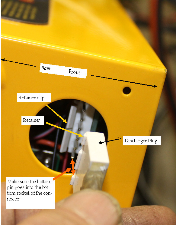 | | | plugging in the discharger |
To avoid any confusion as to the correct way to plug the discharger into the charger,this photo shows the correct orientation and relationship of the charger and discharger connections.
(Posted 3/11/2014 by mikey) |
Cycling the pack in the car | 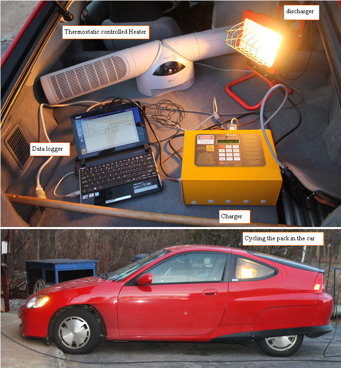 | | | Cycling the pack in the car |
As we look at what we should do with all the new code space and non volatile memory that the new micro controller has available, we decided to make the cycling of the pack a better tool.
The number of automatic cycles will be setable between 1 and 3 cycles. The charge and discharge final data as to start voltage end voltage time, mAh to charge, discharge time, end voltage for each cycle will be stored in eeprom. Two pages of data can be stored for, the 3 cycles, so one can be kept as a reference,and the new cycle will also be stored. This way the pack condition can be captured, and one will be able to compare cycles from previous cycles to the current one as a way to see if the pack is continuing to improve.
I ran a cycle in my car last night which was 25 degreesF
The electric heater was set for 65 degrees, and it was able to keep the pack at 50 to 55F during the process. It was a bit tight back there, but not impossibly so.
(Posted 2/20/2012 by mikey) |
Discharger special harness | 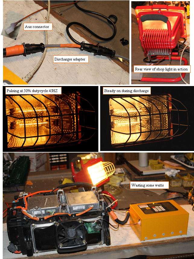 | | | New discharger in action |
The discharger is basically in parallel with the charger output wires going directly through the fuse to the pack.
The splice in this case was made inside the connector strain relief, which is tricky to do well.
The light aluminum enclosure got to a max of 170F, which could burn your skin, but because of the stand and rubber handle, it is safe to use as long as the ambient temperatures are not too high.
The pulser 50% dutycycle mode is for determining internal resistance.This measurement of the very low internal resistances of the subpacks needs to be made right on the battery terminals to eliminate any voltage drops through fuses or connectors.
This approach to the discharger is Rugged, can work with all batteries in the 100-220 V range, encloses the hot bulbs where they are safe from damage and has a case designed to dissipate the heat that is generated. The Power mosfet is also protected and in a cool place in the wiring box, and it has a nice output cable that can tie directly into the discharger adapter cable.
(Posted 1/21/2012 by mikey) |
Better solution | 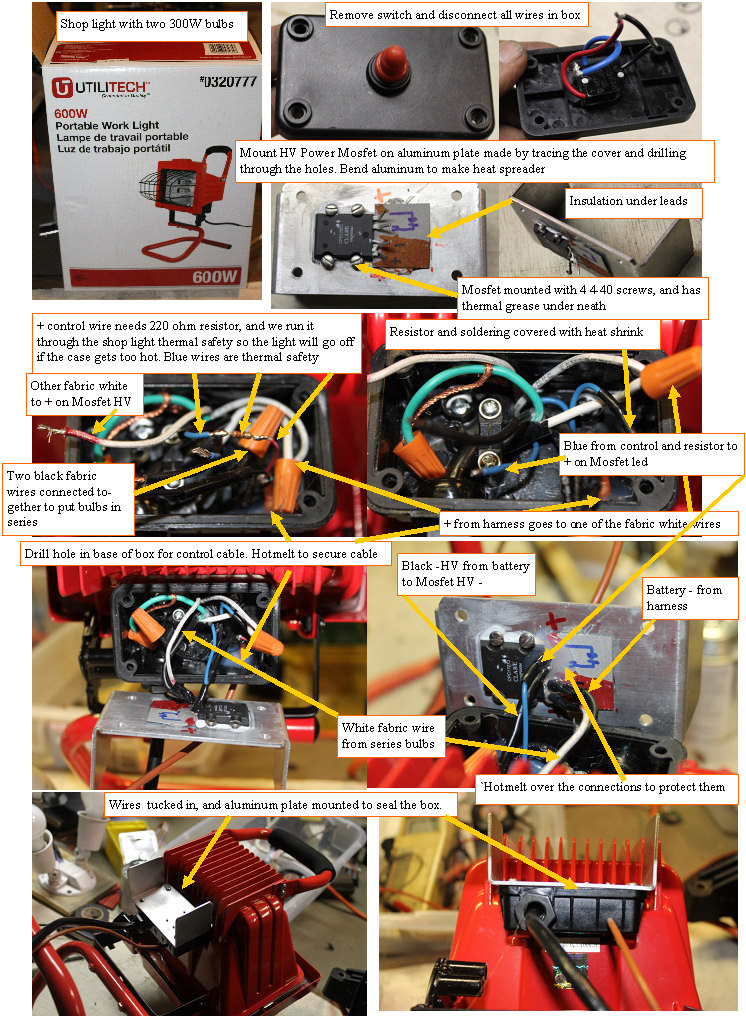 | | | Modified shop light is better solution |
One of the guys that bought a charger asked if a shop light could be the discharge load, and the answer is yes if it is the right kind.
The shop light shown, is sold at Lowes and has two 300W bulbs. I bought one for ~$24, and went to work on it.
First opened the wiring box on the back, and disconnected all of the wires except the green ground wire.
Using an ohmmeter I determined that the white and black high temperature wires connected to the bulbs, and proceeded to connect the two black together to put the bulbs in series.
I removed the pushbutton switch, and used the black cover to mark the outline and hole positions in an 1/8" thick aluminum plate.
Drilled 4 holes to mate up with the power mosfet mounting surfaces, and the 4 mounting holes. Cut a notch out of the top two edges of the plate so it would clear the lights back heat sink.
Bent the two tabs out to help any heat generated to better dissipate. Drilled a small hole for the control cable under the box, and after putting a small zip tie on the cable, aI hotmelted the cable inside the box to stop and rotation or motion.
The white(+HV) from the harness was connected to one end of the series bulbs, and the other was connected to the + lead of the mosfet HV side.
The black (-HV) from the harness goes to the - lead of the MOSFET HV side.
The control cable Black wire goes directly to the MOSFET Opto input - lead, and the red control wire goes through a 180 ohm resistor, and through the blue wires of the shop light thermal cutout switch. The other blue wire goes to the + opto input of the MOSFET. The Mosfet lead area has a small piece of fish paper insulation, and after soldering the whole terminal side of the MOSFET is covered to protect the leads and connections, The aluminum cover with MOSFET is mounted on the box.
Wire the AUX connector to the control wires, and you are good to go once the adapter harness is attached.
A video of this modification
(Posted 1/21/2012 by mikey) |
Connecting the discharger to the Pack | 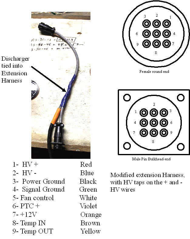 | | | Connecting the discharger to the charger and harness |
The easiest way to connect the discharger is to get another extension harness, that has taps on the two HV wires. The HV wires must be tapped in such a way as to totally eliminate any possibility of the wires shorting, so I pealed back the extension harness outer covering, for a length of 3 inches. The Red harness + wire will have its insulation stripped off just at the beginning of the 3 in opening in the harness sheath. The discharger + wire is twisted with the harness + wire and is soldered and taped with a minimum of 3 wraps of black electrical tape.
The negative discharger wire is attached to the blue -HV wire at the other end of the exposed 3 inch area, in the same fashon as the + wire. After the spliced wires are tapd over, the whole harness splice area wante to be taped with another 3 wraps minimum of black tape to secure and protect the now special discharger extension harness.
(Posted 1/13/2012 by mikey) |
Adding the Aux connector | 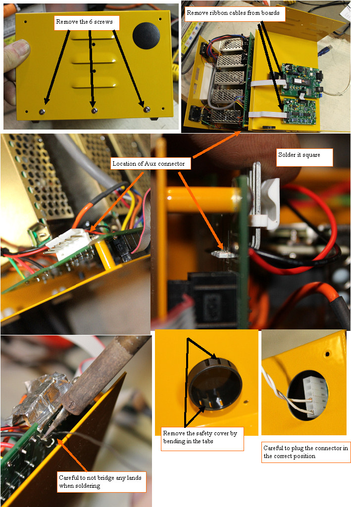 | | | Installing the AUX connector |
Ok, I am a dummy for not putting the connector in the board, but when I was building these chargers, I did not see the dis charger as a use for the port, and was only seeing it as a way to increase the voltage for 300V+ packs, and out of the 100 chargers, no one wanted that, so I decided to leave it off.
OK, My bad, but now how do we get it done.
The connector is able to be soldered to the board without removing all the power supplies and interconnect boards if you are careful.The first pin will set the angle that the connector is mounted at, so be careful to hold it square when completing the first solder joint.
Be sure to carefully inspect the connections to assure that no solder bridges have occurred between adjacent pins or traces.
Anyone that is uncomfortable with soldering this, can send the charger in a well packed flat rate box, and include $28 for the return shipping,and $25 for the upgrade kit (larger microcontroller with latest code, and the new port cover) and I will install the connector and microcontroller and get the charger ready to go with new software and calibration for you and send it back.
(Posted 1/13/2012 by mikey) |
|
