Battery packs exposed
The construction of the two packs is examined and compared, as well as some tips on keeping the pack in good condition.
WARNING, you can be killed or hurt fooling with the battery pack. Don't even think about working on or removing the pack if you are not fully confident in your knowledge of electronics. Get the service manual and electrical manual, and follow the procedures for safely removing the pack from the car.
The HV switch needs to be off whenever the pack is being worked on. The development of tools and hardware to replace defective cells will also be discussed.
|
2006 and up civic packs
|  | | | civic dual subpack construction |
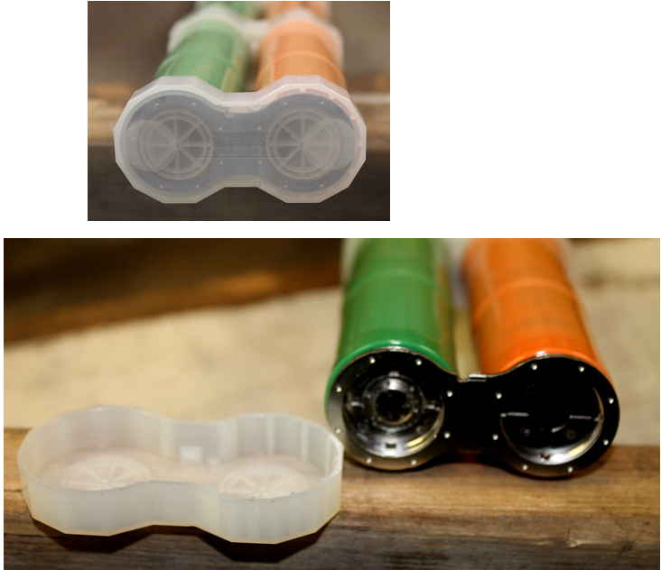
many people have asked if the MaxIMA and other replacement sticks can be used in the later civic packs. The answer is maybe.
The sticks them self are actually 2 of the 6 cell sticks, but instead of the big screw connections that we see on the replacement sticks, we see a welded buss bar making the far side connections. The sticks also do not have the PTC sensors. I would expect that a copper buss bar could be used, but the end cap would not work as designed, so the stacking of the sticks could have difficulties. If I ever get a pack to play with, I will design a solution. |
Lead acid battery failure examined
|  | | | Looking into a sulphated lead acid battery |
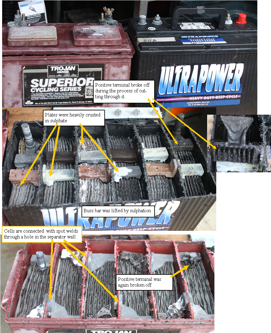
Had some sulphated lead acid batteries that I was going to trade in, so I figured that I may as well get my moneys worth and see how they are made, as well as what was going on in side.
I got out my saws all and carefully cut off the top of two different brands.
It looks like the + terminal is susceptible to the plates corroding right through, and the sulphation can be so severe that it warps the plates until they short, and can lift the big buss bars to the point where they break off.
Not something that will recover very well, so we gave up on the rest and junked them all. |
Testing the sticks at the cell level
|  | | | testing to the cell level at currents similar to the car |
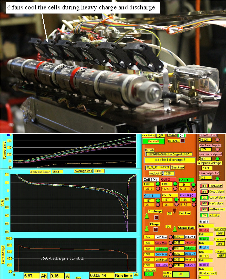
I revived my labview based stick tester and will be using it to test the new MaxIma sticks.
Here is a trace of a stock stick at the 75-80A load. Note that we see 5.8Ah and a temperature rise to over 120 F |
MaxIMA stick full discharge
|  | | | MaxIMA full discharge |
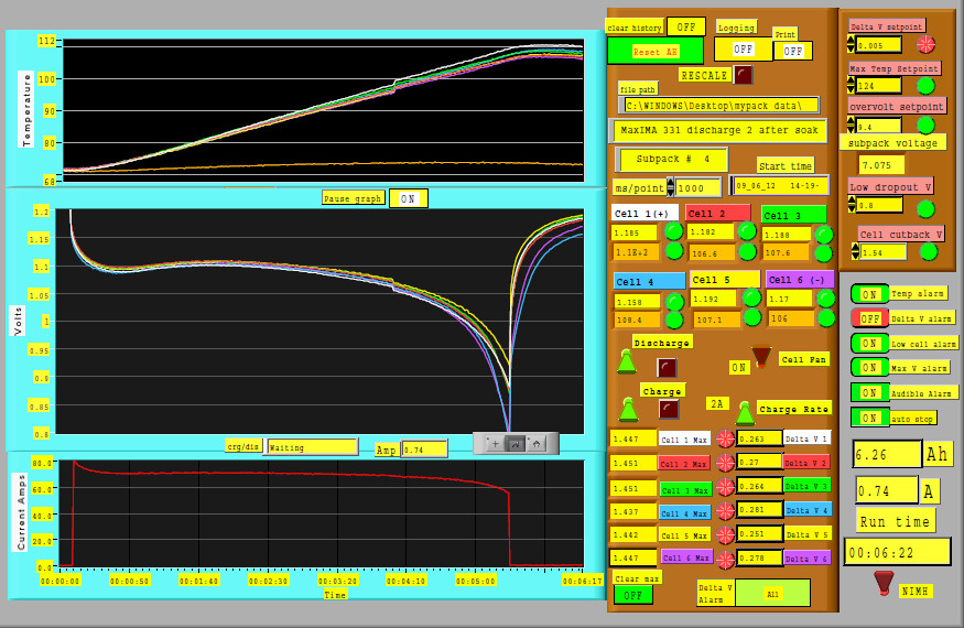
A typical discharge graph for one of the MaxIma sticks. The little wiggle in the trace is caused when labview stops recording the signal for a few seconds while writing a PDF file, and is not a problem in the battery. We see nearly an additional AH of capacity, a higher discharge voltage (less Internal resistance), and less heating even with the additional AH. All good. |
Bumblebee battery replacements for the stock subpacks
| 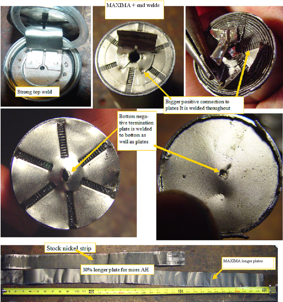 | | | Max IMA batteries show improved internal construction |
Several people have picked up the ball that was dropped by Hybrid battery repair, and are offering new sticks for the civic and the insights, so it is time that we see just how well the sticks are built and how well they perform.
I got 4 sets of 20 subpacks from Bumblebee, and am in the process of evaluating the performance, but we also know that the construction of the cells is a big factor in how well they can handle the currents involved with use in a Hybrid car. The first photo shows the inner cell construction of the MaxIMA cell
more and longer weld points on this cell allow the current to flow with lower internal resistance, so in theory that should translate into less voltage drop under the same load as well as less heating. |
Inside the cells
| 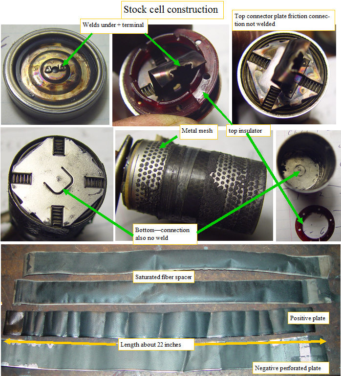 | | | Insight 6.5AH cell inside |
Ok now that I have a good electrical test fixture and have identified a cell that was shorted, recovered, but not back to full capacity, it is time to take a look at the insides of the cell.
The first thing that jumped out at me was the really nice welds. they are deep, show little discoloration in the heat effected zone,with no surface oxides, so they were probably done in an inert gas. The welds were so strong that the sheet metal tore rather than the weld separating.
I made a test fixture to see how much force it would take to "crack" the stick at the cell to cell boundary. Amazingly I was not able to break the welds, even up the the 300 lb max that the scale would take. I had to bend it back and forth 4 or 5 times to get the welds to break out of the metal.
I sanded of the weld stubs, and put the cell in a vice to drain out all the energy.
I turned the cell in my lathe and cut off the top.
The top inner welds were also solid, but I was a bit surprised to find that the top terminal and bottom terminals were simply pressed into the spiral wound plate.The cell must have been assembled in a press to give adiquate contact pressure. I carefully unwrapped the perforated nickle strips which measure about 24 inches. I looked at the plates and separator blotter material, and saw no signs of holes or burned areas(Capacitor Zapp), so this somewhat supports that the capacitor discharge did not blow any holes.Very interesting. |
Seprating the cells for reuse
| 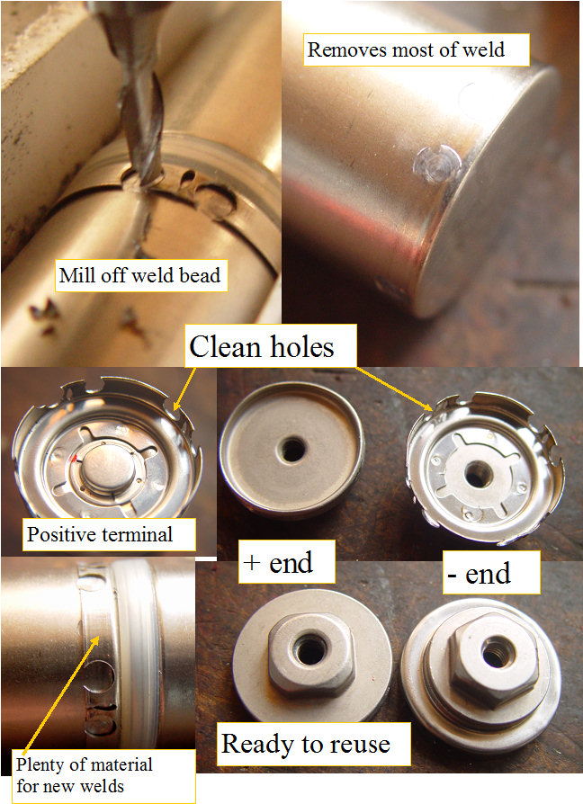 | | | Deconstructing the subpack |
Ok I can test the subpacks down to the cell level, so the bad cells can be identified, now how do we get the cell replaced. Grabbing the stick with plastic strips in the milling machine vice, I milled off the welds being careful to not machine into the stainless steel case. Once the welds were removed, the cup just slid off the underlying case with hardly any force required. The case only needed a light sanding to make it like new. The two end caps also were quite easy to remove and they were left in a reusable condition.
All of this is good news. With a proper fixture to hold the sticks, I could separate the end caps and cells on a whole stick with everything ready to become part of another subpack.
No new parts required.
Time to get on the welding machine. |
How it is wired
| 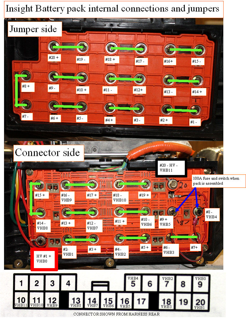 | | | Insight pack internal connections |
Wanted to do some charger/discharger test on a pack that was pretty bad, so I took off the covers, and made this chart, which should be a nice road map for any battery explorers.
********Danger*********
Adding the jumper across where the big fuse and switch was located as shown here removes any protection from shocks or short circuits, so proceed only if you know what you are doing. May be better to use a DC rated fuse in the jumper to maintain short circuit protection.
************************** |
PTC strips exposed
|  | | | Funny how we assume what is inside |
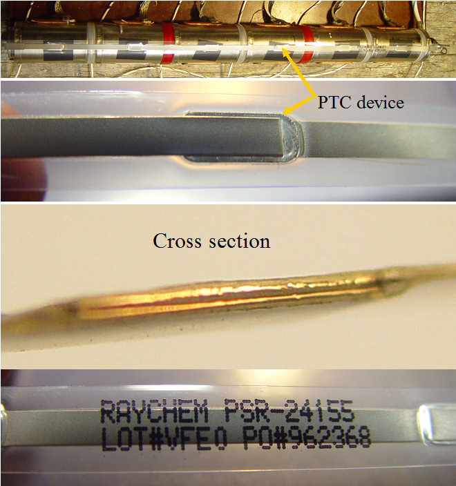
Finally got a look under the black and clear covers of the PTC strip.
It turns out it is really 6 discrete PTC devices that are connected by stainless steel strips, so the active temperature sensitive area is located right in the center of the cells.Very interesting, I will run a resistance to temperature profile on one, and see what the actual characteristics are.
|
The PTC thermistors
|  | | | Protecting against a short like a self resetting fuse |
Several years ago I did some experiments to figure out what the red thingies on the battery packs were, and what they are for.
I hit one with a heat gun, and saw the resistance shoot up from ~ 160 ohms to over 600 with a quick blast. I explained my findings on Insight central, but someone else tried the test in an oven, and was not able to duplicate what I found.
I finally found myself with a loose Insight side terminal plate in my hand, and decided to put my original theory to a different type of test.
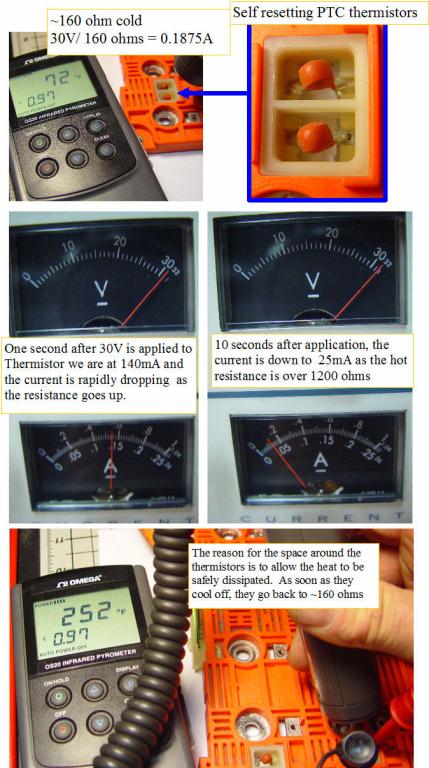
I set up my lab supply with 30V, and the current adjustment was set to the 1 A maximum for the supply, so no power supply current limiting would be involved.
I clipped two probes to the thermistor leads, and used one of the banana jacks as an on off switch. On first application of the voltage, the current pulsed up to just about the expected 185mA, but rapidly over only a few seconds the current dropped to only 25mA and the thermistor was at 250 degrees F. I held it for a minute, and the thermistor stayed at the 250 f.
If the battery tap cable was crushed and all wires shorted, all that would happen would be for the battery end plate to get warm. Nice safety. Swap crushed cable, and the battery pack is good to go.
A self resetting fuse. |
Battery current sensor
|  | | | How it works inside? |
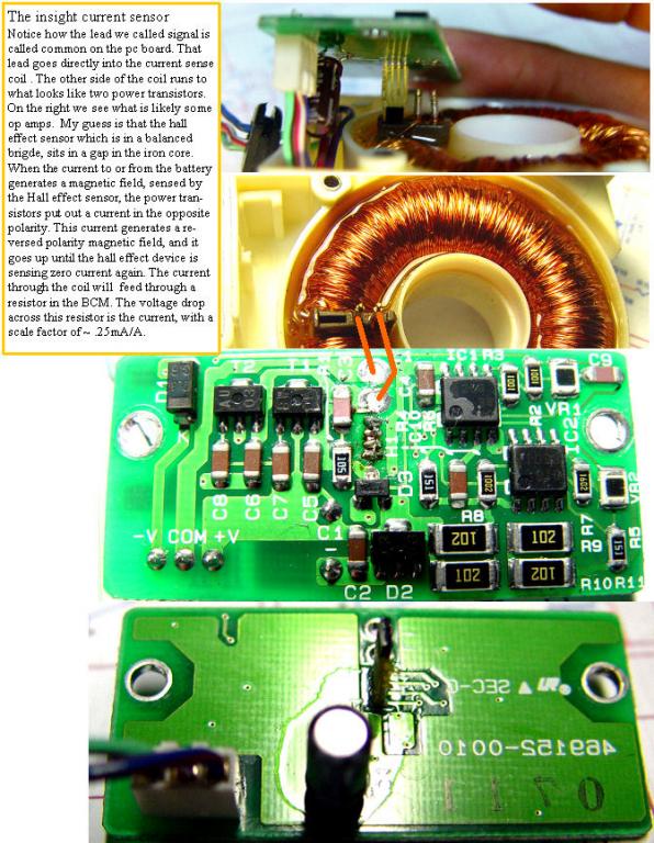
If a larger capacity battery pack is used in the Insight, we must "fool" the BCM into allowing the full AH capacity of the new pack to be used.
I setup a BCM and junction board with current sensor, to determine the best way to fool the current sensor into thinking that only 1/10 of the actual current is passing through it. After a thorough analysis of the system, I determined that the Insight battery current sensor was outputting a current loop signal with ~.20mA/A, and since it is a current loop, a simple current dump resistor to BCM ground should do it. |
Inside the 100A semiconductor battery pack fuse
|  | | | The insides of a high power fuse |
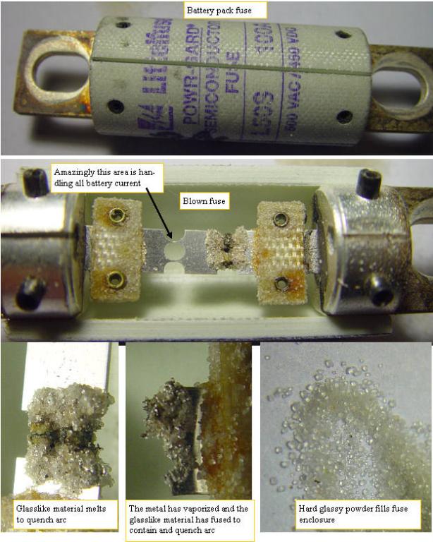
The battery packs of all hybrid cars have a very special fuse to protect the circuits and the pack from short circuit and over current conditions.An Insight owner came over so that I could help him diagnose his IMA problem, and we found tht the main 100A fuse was blown. He had already replaced the inverter stage, which must have been the cause of the fuse failure.
Opening a high voltage high current DC circuit requires a special type of fuse. It is called a semiconductor fuse, but this name is misleading. There are no semiconductors in the fuse, the name describes it's ability to blow extremely quickly so any semiconductor devices it is powering will be protected, and this means rapidly quenching the hot arc that forms when a high power DC circuit is opened. The metal element is similar to a regular fuse, but the fuse is filled with an insulating glass like powder that rapidly melts and quenches the arc.I opened the blown fuse so we could see how it is constructed. |
Did it again for the last time
|  | | | More cooked prius subpacks |
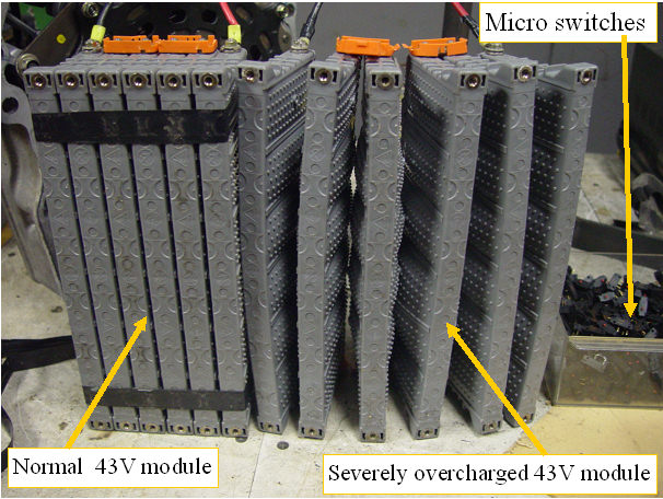
Well I cooked some more prius subpacks. This time was 10A for several hours. I am not going to do this again. I have a lot of microswitches in my surplus drawers, so I will add a switch in series with the pack charging path that will sense the first sign of internal pressure build up (adjustable), and kill the charge when the first swelling is detected.This seems to be around the 100% SOC point. |
A bad Prius subpack explored and fixed????
|  | | | blasting a prius subpack |
Carolyn Coquillette from Luscious Garage in San Fransisco,
( http://www.lusciousgarage.com/ )was kind enough to send me a first gen Prius battery pack. The pack was bad and the codes indicated two bad subpacks.
Carolyn attended one of the Hybrid classes that I was involved with, and is a highly qualified hybrid auto technician.If you live in the bay area, and have a hybrid, you should consider Luscious Garage for all of your service.
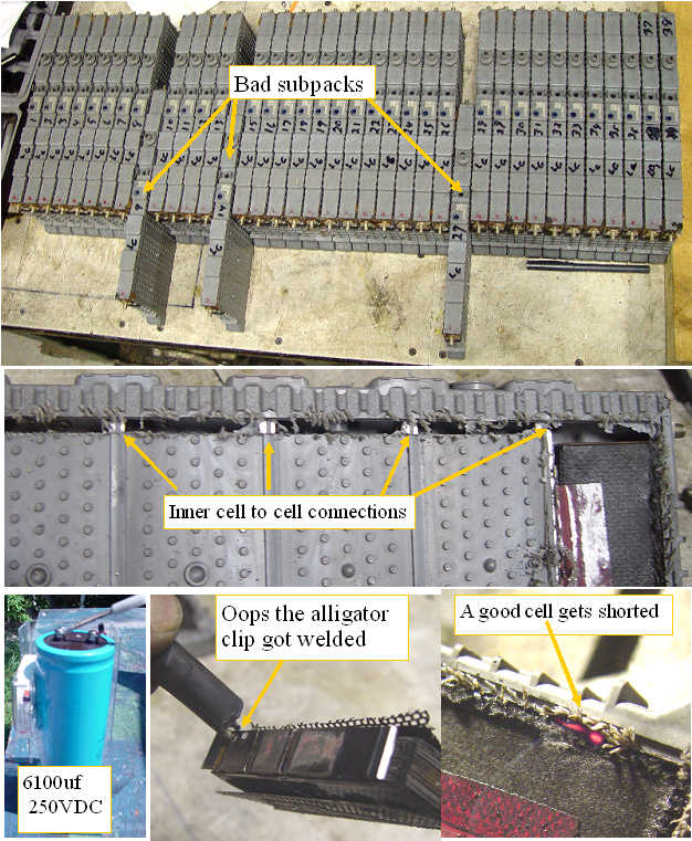
I have not had the opportunity until now to examine a Prius subpack that was actually bad, so I immediately labeled the subpacks, and removed them from the enclosure. A quick voltage test showed two subpacks that were a full 1.2V or more lower than the rest, and one that was about .7V lower.
I put the two bad subpacks on a charger to see if the subpacks would recover, but shortly after the charge seemed to be complete, the subpack dropped back to the same condition, indicating that the subpack likely had a shorted cell.
I used my milling machine to expose the cell to cell connections, and indeed, one cell was at 0 volts while the rest were fully charged.
One must be very careful playing with charged NIMH batteries in a milling machine.
My end mill managed to hit the plates of one of the good cells, and the current lit up the shorted area cherry red.
In my RC modeling days, when a NICAD cell would short, it usually was a symptom of a plate to plate short caused by a nickel whisker.The trick we used to do was to blast away the short by discharging a big capacitor into the cell. Sure enough, I took the shorted cell, and blasted it with 250V from a 6100uf cap, and the cell was able to be charged. Next I took the other subpack with the same problem, and blasted the whole subpack with the same capacitor.
While I do not expect the blasted subpack to be equal to a good subpack, it was nice to see that the initial response was to fix the shorted cell. If ever there were an imbalance condition, this is it. one cell started at zero charge while the rest were fully charged. I will give the subpack some time to equilibrate, and then compare it under load with a good subpack in a series configuration.
While blowing out some plastic chips from the machined subpack, some of the potassium hydroxide electrolyte sprayed past my glasses into my left eye. It burned a bit, and I immediately flushed my eye with a lot of water, and my eye is fine. Batterys are dangerous in many ways.
|
Rebalancing the Insight battery?
|  | | | Long term storage warning |
A common problem with the MT Honda Insight, and to a lesser degree the Civic hybrids is a condition called recalibration. The most common version of this condition shows up as a rapid drop in the battery SOC gauge from some intermediate value to empty. The car goes into a forced charge to bring the SOC back up, which if it happens frequently, can take its toll on the MPG.
One of the possible reasons for this condition is an unbalanced SOC between the different cells in the pack.
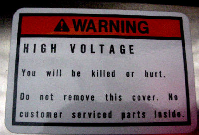
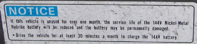
The warning label from a civic battery pack warns to run the car for 30 minutes a month. It is likely that the self discharge characteristics of the cells is not predictable, so some subpacks will discharge to a lower level than others, and there does not seem to be a rebalancing mechanism in place to correct the imbalance once developed?
The civic hybrid battery packs made 2005 or before are a good source for replacement 6 cell subpacks with the PTC temperature strips attached.
|
Insight battery
The insight battery pack is made up of 120 D cell NIMH batteries, grouped into packs of 6 cells. You can see that the air path for cooling the pack is not very open, therefor the cooling of the pack is not very agressive. The pack has a strip of thermal sensing material that is in intimate contact with each cell in the pack. The D cell subpacks are terminated with a large stainless steel nut that can handle the 100A output. This is the special part of the pack, as we have not found a D cell that has similar high current contacts, so cell replacement with new subpacks is not an option at this time. The civic packs up to 2005 are drop in replacements, so you could get one of those much more readily available used packs and rebuild your Insight pack with the civic subpacks which are direct replacements with a more robust cell structure. The 2006 and up civic packs are built differently and are not direct replacements. |
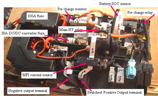
Insight Battery switching/current monitoring
The Insight pack is protected by a 100A fuse, and high voltage DC switching relays. The current into and out of the battery is measured by a hall effect current sensor, and the Current into the MPI is measured by a second current sensor. |
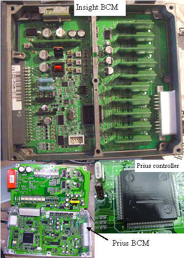
The battery controller
The Prius and Insight BCM modules are quite different. The Insight one is not as complex. The main controller for both is painted over so the part numbers cannot be read. |
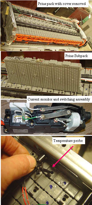
Prius battery pack
The Prius battery system is made up of 6 cell subpacks that are cooled and mounted in a much more practical fashion. The subpacks each have a thermal well, and high current connections. The bumps and sockets on the subpack sides allow a small air gap for the cooling air to pass through. Because the internal pressure in the cells would deform the plastic sides of the subpack, the whole 40 subpack assembly is compressed between two metal plates, so the pressure cannot deform the subpacks, and each subpack has a pressure relief valve. A cleaner easier to service pack for sure. |
State Of Charge (SOC) determination with NIMH batteries
|  | | | IMA system SOC determination |
The terminal voltage of a lead acid or Lithium battery can be used to determine the SOC, since it drops as the battery is discharged.
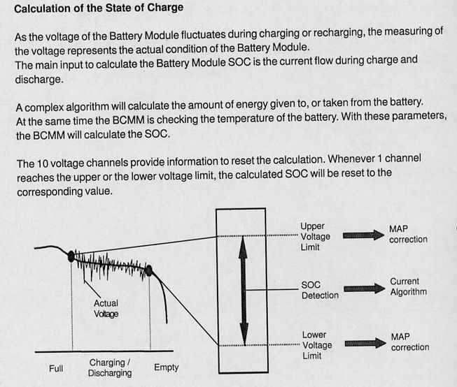
The discharge voltage of a NIMH pack is very flat, compared with other batteries, so the best way to determine the SOC is to measure the current into and out of the pack. The minimum SOC where one of the subpacks reaches the drop out area of the curve is used to start a forced recharge called a recalibration. The full SOC condition can de measured by watching for the voltage change at the full charge point, as well as the rapid rise in temperature when at that point. |
Battery pack monitoring
| 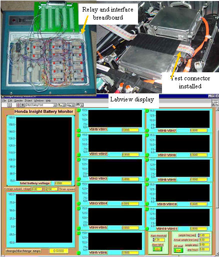 | | | Battery pack monitoring system |
Back in 2001 when I first started being active in the Insight on line community, I was concerned about the life of the battery pack, especially the issue of recalibrations. Our understanding of the reasons for the "recals" have not advanced much since then.
I designed a battery monitoring system that used relays for isolation to read each of the 14.4v monitoring points in the pack. The connection to the pack was accomplished with a special spring loaded back probe that just clipped onto the battery. A Labview based data acquisition card and software scanned the taps and recorded the voltage graphically.
I fully expected that my pack would eventually start having the recal issue and wanted to be ready. I am now nearly at 100K on my car, and still have not experienced a single recal. Honda says that gradually accumulating errors in the coulomb counting SOC software is the reason that recal's happen, but I ask what causes the errors? My intuition says that one cell in a subpack is of lower capacity, and since the pack is one long 120 cell series string, that one cell will cause the whole pack to have less capacity than the system expects. When the BCM senses the weak cell dropping voltage as it becomes depleted, the system stops assisting and starts charging to prevent the cell from becoming reverse charged which is instant death. A smart system would have the ability to balance the pack by charging that cell more than the others. Unfortunately since the cell is in a 6 cell subpack, that is not possible with either the Honda or Toyota systems.
|
What happens to a Prius subpack when you overcharge it?
| 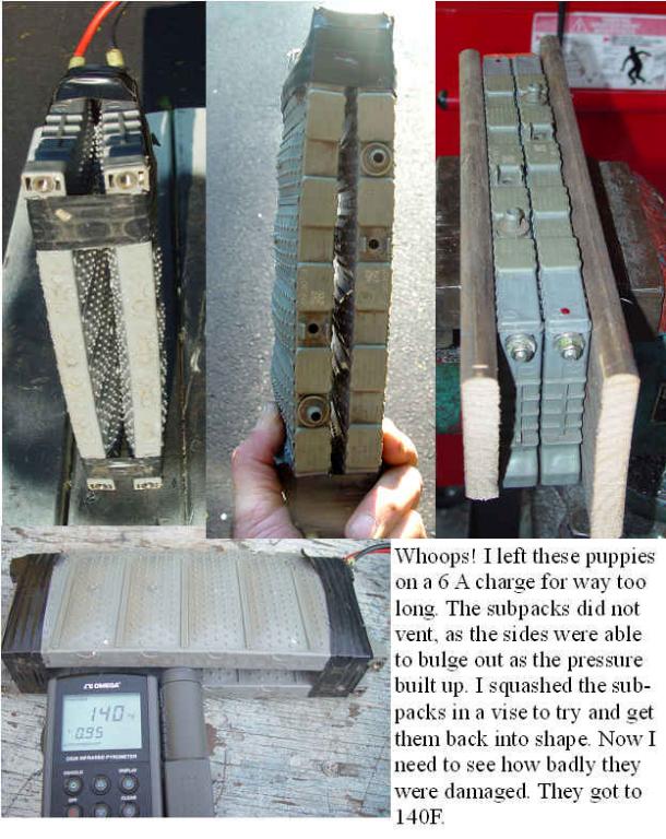 | | | Opps! Cooked some prius subpacks |
Well it happened again. I put my dual prius subpack on my 6A 75V solar panels for a quick recharge between the solar dish runs, and forgot it for several hours. When I finally remembered it, the black tape holding the subpacks together had nearly ripped apart and the cells swelled up with a lot of internal hydrogen pressure. Usually the subpacks are clamped tightly so they cannot swell, so they would vent the gas instead. I measured 140F between the packs, and submerged them in water to cool them.
Even after an overnight cool down, the subpacks were still swollen. I drilled six holes in two boards, to clear the locating tabs, so the clamping pressure would be uniform, and squeezed the subpacks together. Several hours of clamping, and the cells were back to normal shape, with no signs of any fluid venting.
I used the same packs to run my next canning run, and also to run a 30A 12V heater, and they seem to
Have been using the same dual pack in my lawn tractor for the last 2 years and they are working fine.
Some tough batteries for sure. |
Mikes Blogs: |