10. The first MIMA operational testHere it is what you have been waiting for, lets see if MIMA is working. Start the car. The battery charge should be at least 3-5 bars. The display will do an initialization where it lights the leds while waiting for the car signals to stabilize.
With version 1.5 software and later, the joystick will need to be calibrated before the system will work, but I have already calibrated your card and joystick(s) before shipping as part of the test procedure.
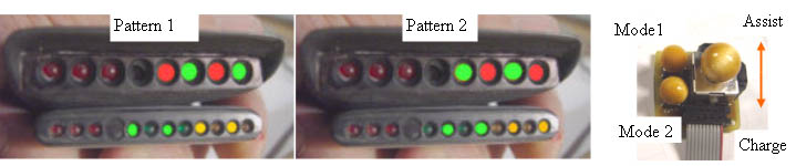
When the display panel leds go out, MIMA is ready. With the car idling in neutral, move the joystick to the assist direction. The cars assist bar graph should show that assist is happening, and the gasoline engine should rev up as the electric motor power is turned on. The display should show the MIMA active led on, and the assist leds should all light. If this works, you are MIMA equipped, and can operate MIMA manually, but PIMA and ABC is still not tested.
|
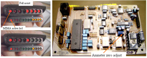
Ammeter zero level
I have approximately adjusted the ammeter zero level on your card on my car, but each car is slightly different, so we will now zero the ammeter. First make sure that no fans or A/C, lights, radio, or other loads are operating. Quickly tap the mode 1 button on the joystick. The mode 1 active led should light. This mode disables background charging. All other leds should be out, but one assist or one charge led may be on.
Adjust the Ammeter zero adjustment potentiometer until all of the amp leds go out. This is a sensitive adjustment, so turn slowly. If more red/amber leds come on while you adjust, you are going the wrong way.
|
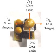
Jog the calibration
To jog the calibration, you must be moving over 19 mph, and be in PIMA (mode 2). A single jog, is moving the joystick to the desired position, then allowing it to return to center. Each time you do this, you change the set-point in that direction by 2 units out of a total of 118. |
Installation and introduction: |