The following tools and equipment will be needed to complete this installation: Roll of black electrical tape Metric wrenches #2 Phillip screwdriver MIMA upholstery tool Torque driver #T30 Digital multimeter, even a cheapo $10 radio shack one will be good enough. MIMA test adapter
Shift console removal Unscrew the shift knob by turning it counter clockwise until it is off the screw.
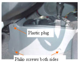
Remove the four screws (2 on each side) at the corners of the shift console cover, and pop out the plastic plugs with the upholstery tool. The shift console cover should now lift right out of the car. The plugs are in there pretty good, so pry carefully with the tool provided. If the plug breaks, you will have to get a replacement from your Honda parts department.
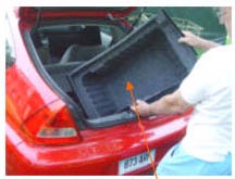
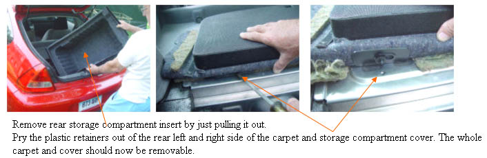
Remove rear storage compartment Danger you are about to open the High Voltage area of the car. Always leave the battery switch off while the cover is removed.
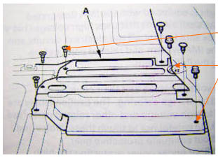
Remove all the torq and 10mm bolts from the rear covers.
opening the IMA box
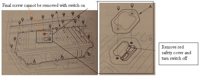
First open the metal cover in the center of the rear IMA area, and after pulling the red plastic cover off the switch, flip the switch to off, and replace the red cover to keep it off.
Continued... Once all of the screws are removed, the switch turned off, and the final screw removed, you must also remove the small aluminum cover to the right (from rear) of the electronics area.
This cover has a variety of different bolts and screws the plastic screws on the front look like standard Philips, but may not unscrew, and will need to be pried out. There are two bolts on the back, one is hidden by the carpeting. Finally the plastic push plugs will need to be pried out. Once this panel is out, the big cover should easily lift out. Final step is to remove the negative wire from the 12V battery(caution when this is disconnected, the rear hatch can only be opened with a key)