3. Threading the Harness | 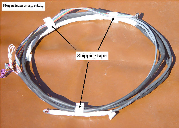 | | | Only remove the shipping white tape. |
The harness is shipped with white tape over all exposed wires and pins, to allow the diameter to be small enough to pass through the wiring tubes.Do not remove this tape, until the harness is threaded through.
The harness is also is taped into a circle for shipping with more white tape. Only the shipping white tape will be removed at this step.
|
Getting the harness ready to thread through
| 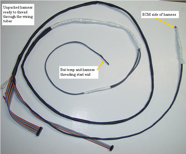 | | | Ready to thread through the tubes |
The shipping tape has been removed, and we have the wiring tubes in place. The white taped areas are holding the plug in pins and adapters tightly against the harness proper, so that the diameter will fit through the wiring tubes. Start with the temperature probe end and carefully thread the harness through both wiring tubes. |
Threading the harness through the tubes
|  | | | Threading it through |
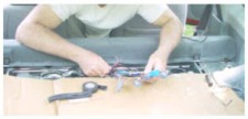
The harness in general is fairly rugged, but the tight areas that the harness must be fished through, and the lumpy nature of the harness, make it extremely important that you do not try to just pull the harness through the wiring tubes, and instead you will push with one hand, and gently pull with the other. The harness is a snug fit, but has been tested to make sure that the bundle can pass through the tubes.
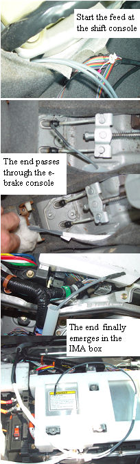
Once it gets tight, a slow gentle push, with one hand while pulling gently with the other, and it should slide right through. It may be necessary to prevent the tubes from moving, by taping to a nearby harness. I will feed it into the front end of the shift console to e-brake tube, while gently pulling the wire out of the e-brake side with the other hand. Once the temp probe is out enough to feed into the rear tube inlet, the same right hand feed in, left hand gentle putt, also feeds it into the rear tube. Having someone there that is gently pulling it into the rear area really helps with this three handed operation.
The multi-wire harness is quite strong in the longitudinal direction, but can be damaged by a tight bend which could put a lot of strain on only a few internal wires. That is why we pass it through both tubes at once.
Slow and gentle is the secrete to no damage.
|
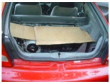
Cover the work area
Because of the danger of dropping tools or having the harness ends getting into the electronics, a large piece of cardboard to cover the work area is recommended.The rear rug, or front foot well rugs will also help. The electrical connections in th HV box are all safe, but you dont want to take the chance of a metal pin, or other object falling down into the box.
|
Comfortable position
I found that the easiest work position for me was to kneel on the two front seats, and lean between the seats into the rear area. |
Unwraping the white tape
|  | | | Checking for damage |
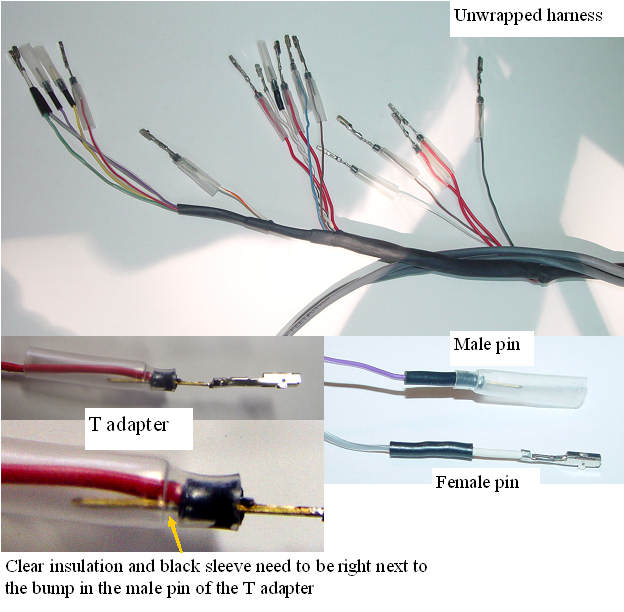
Once the cardboard cover is in place, carefully remove the white tape on the harness, to expose the harness pins and adapters. The three basic harness terminations each need to be inspected to make sure that nothing has moved during the taping/un-taping process. If the insulation has moved, simply push it back into the proper position, as the connector will prevent it from moving once installed. |
Installation and introduction: |