8. Overall wiring test | 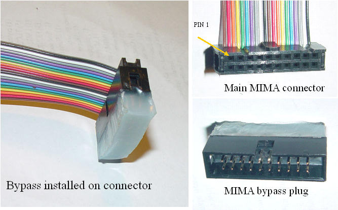 | | | Bypass plug |
One of the requirements of MIMA was that it allowed normal IMA to operate without interference from MIMA. Since we have cut two of the key wires in the IMA control system, we must always either provide a substitute signal, or connect the original signal to the car. The MIMA design uses relays to perform this switching function so the signals are always connected when MIMA is un-powered or turned off. If the MIMA board is not connected to the MIMA ribbon, a bypass plug must be plugged in to the main ribbon connector in it's place to reconnect the wires that we have cut.
At this point, check that the HV area is cleaned up and that there are no tools loose back there.
I have provided two bypass plugs. One is potted in Hot-melt so the wires are insulated, the other has the bypass connections and all other connections exposed for easy testing. We will plug in the test connector for the following test. The black colored side of the connector should be located on the side of the ribbon that has the brown ribbon wire on the ribbon edge, or the Pin (1) one side.
All of the MCM and BCM and ECM connectors need to be plugged back into the modules.
Turn on the main HV power switch, and assume that everything in back is hot.
The test plug must also be plugged into the Main connector, and carefully prevented from touching the cars chassis.
|
The test plug
|  | | | Testing the connections |
Prior to connecting the MIMA system, we will confirm that the signals are properly connected. |
Test 1: Confirm car starts, and no IMA codes
The 12V battery should be reconnected at this time.
Start the car. The car will probably start with the IMA motor, but may also start with the 12 V starter.
Since the harness was disconnected from the MCM and BCM, the SOC will probably be at empty, and 4 green regen bars will be lit as the car tries to charge the battery. The charge will continue until the BCM determines that the pack is in fact full, at which point the SOC gauge will do a positive reset and rapidly go to full.
If you see any codes, turn off the car, and do the MCM reset below.
If no codes go to test 2.
This test also confirms that the MAMODE1, and CMDPWR connections are being properly umpired by the test connector, and therefore are connected to the proper Main ribbon connector wires. Since they are jumpered, they could still be reversed, but we will discover that once we do the power on test.
|
MCM reset
After the reset, the IMA battery SOC indicator may show no charge. This is normal, and will correct itself, once the car is driven several miles.
A more aggressive (and wasteful) technique is the forced charge.
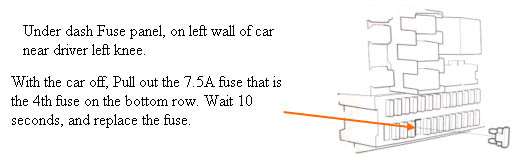
The Forced charge procedure is to pull the #15 EPS fuse (40A) from the under hood fuse/relay box, then start the engine in neutral and hold the rpm at ~3500 rpm till the battery gauge becomes normal.
So far the simplest techniques is to just drive normally for 5-10 minutes, and the batteries should charge right up.
|
Test 2: confirm 13.6 volts
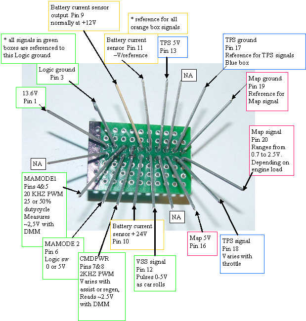
Connect the black or negative lead of the DVM to pin 3, the logic ground terminal, and the positive lead to pin 1 the switched 13.6V supply. Start the car. This voltage should be between 12.6 and 14VDC.
|
Test 3: confirm VSS
The negative lead is left connected to pin 3, and the positive lead to pin 12 the VSS signal. This signal will be either a low (0V) or a high( 5V) when the car is stopped. As soon as the car begins to move, the signal will alternate between low and hi, and switch faster as the car moves faster. With the leads connected, engine running; push the car in neutral, or drive the car slowly, while watching the meter to confirm that the signal switches high and low. If it switches, the VSS connection is good.
|
Test 4: confirm battery amp monitor connections
Move the negative lead of the DVM to pin 11 batter sensor negative. Connect the positive lead of the DVM to confirm that pin 10 measures the +24V.
positive lead to pin 9 to confirm that the amp signal is ~12V. The voltage of this pin will be 12V if no amps are being put into or removed from the battery, so you may need to take a short ride to confirm that this voltage changes with the assist and charge bar graphs.
0.02 Volts per amp, + for assist, - for charge. That would be 14V for full assist, and 11V for full charge. All we need to do here is confirm that this voltage changes when the bar graphs change.
Drive to charge the battery to at least 3-5 bars, as we will need to try the assist during the operational test.
|
Confirming Pins 4&5 the MAMODE1 signal
This signal is best viewed with an oscilloscope, as it is a 20kHz PWM pulse train, but it will measure about 2.5V with a DC DMM. The negative lead of meter on pin 3. |
Confirm Pins 7&8 CMDPWR signal
This signal is also best viewed with a scope, as it is a 2kHz PWM that runs from 10% dutycycle to 90% dutycycle as either assist or regen is requested. It will also read ~ 2.5Vdc with a DMM, referenced to pin 3. |
Confirm TPS sensor signal Pin 18
Connect the meter ground to Pin 17, and confirm that Pin 13 the sensor power pin has ~5 volts. The TPS signal on pin 18 should range from ~.5V to nearly 5V at full throttle.
|
Confirming the MAP signal on pin 20
The MAP signal ground on pin 19, is where to connect the DVM negative lead. Confirm that the sensor 5V is present on pin 16. Confirm that the MAP signal on pin 20 varies with engine load. |
Installation and introduction: |