|
4. Removing the pins from the Multilock connectors | 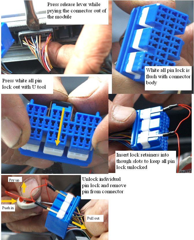 | | | How to remove the pins from MCM and ECM connectors |
The process that will be used to remove the connector pins, needs to be understood and reliably executed for this installation to go smoothly and quickly.
|
How the connectors work.
|  | | | How the Pins work |
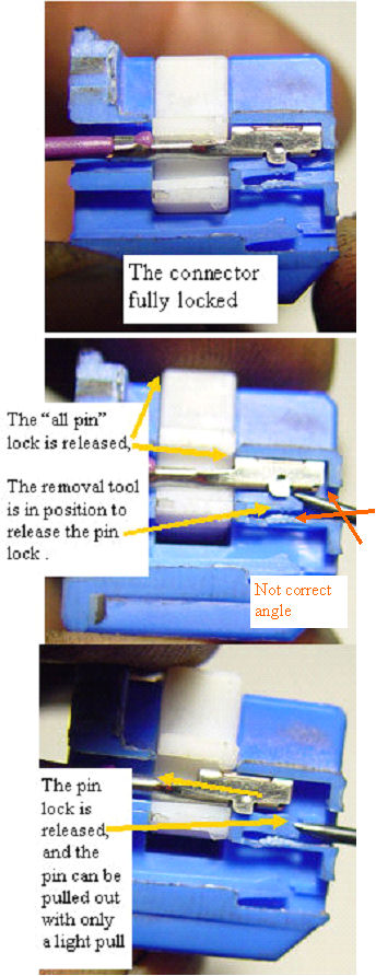
The difficult part of removing the pins has to do with the way the connectors are constructed, and the inability to clearly see how they work inside. I sanded off the side of a connector so the inner workings could be observed, to at least let us see how they work.
Two areas seem to cause most of the problems that people have had in trying this process.
The first is the pin lock release procedure. There are three points where the tip of the removal tool can grab. The pin lock pawl as shown in the photo is the correct one. The angle that the tool is held at as it is put into the connector must allow the tip of the tool to engage the locking pin just as shown in the photo. If the entry angle is too steep, the tool can catch on the leading edge of the metal pin, and could damage it if the pin tool was forced. If the tool is inserted too straight in, it could go under the pin lock, and would not do anything. Visualize the tip and the release pin as you put the tool into the connector, and you will get it right each time.
The second problem has to do with the actual pawl release and pin removal. The pin is metal, and has a rather sharp rear edge where the two lock systems engage it.The plastic of the pin lock pawl and the white "all pin" lock block is pretty soft by comparison. If you are pulling out on the pin while it is locked by either of the locks, the metal will dig into the plastic lock, and stop it from releasing.If the pin is pushed into the connector or left slack,no problems will occur. Don't pull until both locks are released. If unlocked properly, the pin will pull out almost effortlessly. If you have problems pulling a pin,it is a pretty sure thing that you got the lock stuck by pulling prematurely. Push the pin back in and try the pin release again, and it will likely work just fine. |
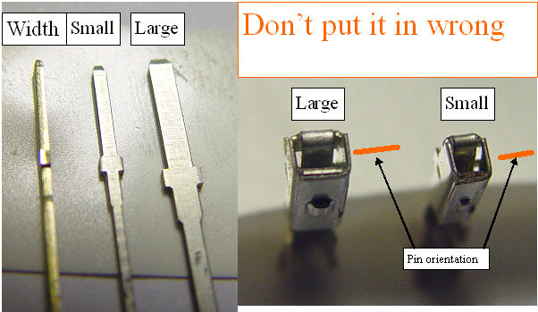
The pins are rectangular
|  | | | Plug in the pins correctly |
The pins and receptacles used in the connectors come in two sizes, The larger of the two is called out as LARGE in the connector drawings. Both the large and small have the same thickness. The large is designed to carry more current.The male pins are normally embedded into the controller header, and the receptacles are held in the connector so that there is not much chance of plugging them in wrong. Unfortunately the MIMA harness uses the pins and receptacles differently, and it is up to you to assemble them correctly.The large pins are no problem as the width to thickness ratio is so large that you can't plug them in rotated by 90 degrees, but the small pins can actually be plugged in 90 degrees from the correct position, which could deflect the stock receptacles spring contact beyond the yield point, and prevent the receptacle from making reliable contact if ever you need to remove the MIMA harness and put the receptacle back into the connector. Please make sure that you insert the pin into the receptacle in the correct orientation. This is why I used clear tubing for the pin insulating sleeves. |
Installation and introduction: |
|
