The ECM is in a bad place to work, right under the passenger's feet. To remove the ECM so we can get at the connection points, is no small task, but with care, and patience, should go smoothly.
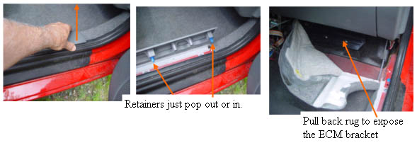
We start by removing the plastic cover over the door jamb, by pulling straight up, so the plastic clips pop out of the holes in the jamb. Then pop the upholstery rivet on the top side of the rug with the provided tool. Remove the plastic rivets that hold the rug under the door, and fold the rug and plastic bracket out of the way.
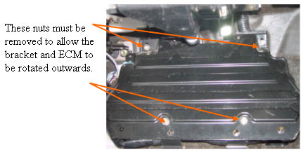
Getting the ECM separated from the bracket Remove the two 10mm nuts at the top, and the two 10 mm nuts at the bottom of the ECM bracket. Lift the bottom of the bracket up and out, and rotate the assembly counter clockwise, to get at the final two 10 mm bolts that hold the ECM to the bracket from underneath. Be very careful not to stress or break any of the wires, this assembly should rotate with little strain on the harness if you do it correctly. Remove the last two bolts that are holding the ECM to the bracket,from underneath then remove the bracket. This is the most difficult step of the whole installation, as the harness is in a bad place to work comfortably. I found it easiest to kneel on a soft cloth just outside the open passenger door while leaning into the car to make the connections.
ECM connections
ECM FAS and MIMA connections
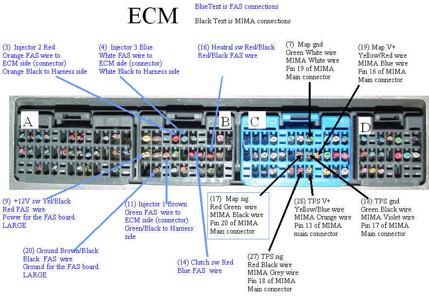
The connections to the ECM are made exactly as the MCM and BCM connections. The position is difficult to work in, but nobody said this was easy. Please print the high res ECM PDF Download ECM PDF
Connecting the FAS relay system
FAS connections to harness
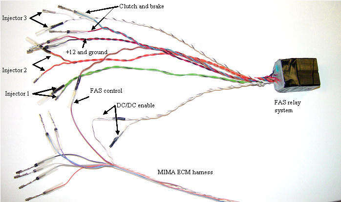
The optional FAS relay system allows MIMA to stop the fuel injectors from firing, and to parallel the clutch switch so that the car will stay in the stalled condition until: 1. The brakes are activated enough times to deplete the brake boost vacuum. The car will automatically restart when this happens so the brakes will always work. 2. You step on the gas. 3. You shift out of neutral. This makes coasting engine off, which can be a great fuel saver, safe. The ECM chart above shows in blue all of the FAS connections. These connections are identical to the MIMA harness connections. Pay particular attention to the two white wires with black stripes. One twisted pair (shorter) consist of two white/black stripped wires, and another twisted pair of one white /black twisted with a solid white. The shorter twisted pair with both white/black striped wires is the DC/DC converter enable wire. These two wires will plug into the white/black wires that are plugged into each other at the end of the ECM harness. The other white twisted with white/black pair is plugged into the ECM connector to open one of the fuel injector wires. The brown wire of the FAS plugs into the brown wire from the MIMA ECM harness, and is the FAS activation line from the MIMA system.
Dressing the wires when finished
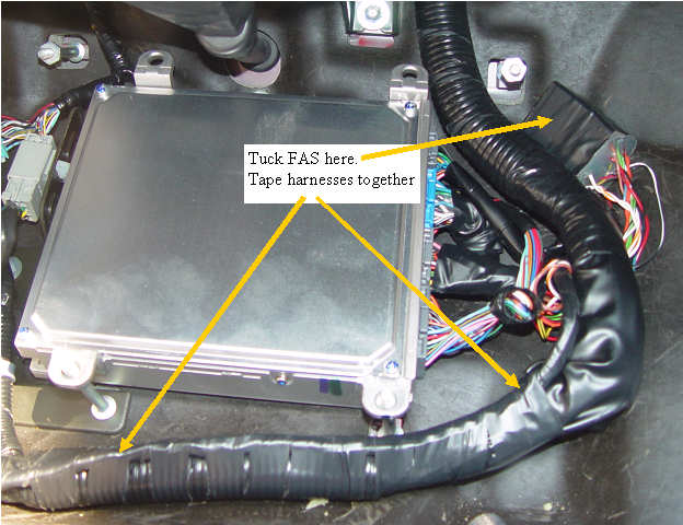
Final harness and FAs relay positions
The passengers foot well area where the ECM sits is pretty tight, so it is important that the new MIMA harness and the existing harnesses are tied together, and in the case of the FAS relay, that it all tucks nicely under the cover with no pinched wires.