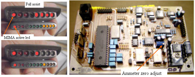
The end of the Plug and Play MIMA, and MIMA2
MIMA introduction
MIMA Operation
MIMA Users Page
Installing MIMA with The Plug and Play harness
FAQ
Installing MIMA with the pin replacement harness
Installation and introduction
1. Disassembly
2. Installing the harness tubes
3. Threading the Harness
4. Removing the pins from the Multilock connectors
5. Installing the rear connections
6. Mounting the MIMA system in the car.
7. Accessing and connecting to the ECM
8. Overall wiring test
9. First power up test
10. The first MIMA operational test
Ammeter zero level
Jog the calibration
11. Confirming temp probe and fan control operation, and final checkout
12. Mounting the low profile display
13. Removing the MIMA harness
software
The MIMA Joystick
The MIMA Display
The FAS system
DIY MIMA L
Cable impedance problem with last MIMA systems.
Learning to drive with MIMA
Hardwired Harness
Theory of Operation

Ammeter zero level

I have approximately adjusted the ammeter zero level on your card on my car, but each car is slightly different, so we will now zero the ammeter. First make sure that no fans or A/C, lights, radio, or other loads are operating. Quickly tap the mode 1 button on the joystick. The mode 1 active led should light. This mode disables background charging. All other leds should be out, but one assist or one charge led may be on.

Adjust the Ammeter zero adjustment potentiometer until all of the amp leds go out. This is a sensitive adjustment, so turn slowly. If more red/amber leds come on while you adjust, you are going the wrong way.


Ammeter zero level