The end of the Plug and Play MIMA, and MIMA2
MIMA introduction
MIMA Operation
MIMA Users Page
Installing MIMA with The Plug and Play harness
FAQ
Installing MIMA with the pin replacement harness
Installation and introduction
1. Disassembly
2. Installing the harness tubes
3. Threading the Harness
4. Removing the pins from the Multilock connectors
5. Installing the rear connections
6. Mounting the MIMA system in the car.
Front end of harness
Connecting the white ground wire.
7. Accessing and connecting to the ECM
8. Overall wiring test
9. First power up test
10. The first MIMA operational test
11. Confirming temp probe and fan control operation, and final checkout
12. Mounting the low profile display
13. Removing the MIMA harness
software
The MIMA Joystick
The MIMA Display
The FAS system
DIY MIMA L
Cable impedance problem with last MIMA systems.
Learning to drive with MIMA
Hardwired Harness
Theory of Operation

Front end of harness

Front end of harness

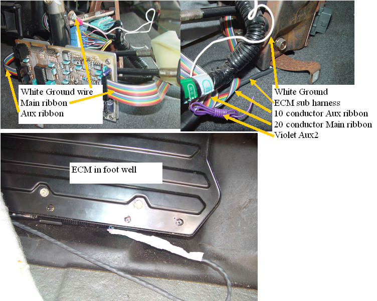
The front of the harness has several breakouts, the large 20 conductor ribbon connector, is the main MIMA controller I/O. It will feed across to the left side of the shift console, and will later plug into the MIMA card.
The 10 conductor ribbon is the AUX output. This port controls the fans, the FAS, and has one undefined output (Violet wire).
The White ground wire is to be connected to the metal chassis of the car.
Finally the ECM connections need to be fished under the rug to the ECM area.