The end of the Plug and Play MIMA, and MIMA2
MIMA introduction
MIMA Operation
MIMA Users Page
Installing MIMA with The Plug and Play harness
FAQ
Installing MIMA with the pin replacement harness
Installation and introduction
1. Disassembly
2. Installing the harness tubes
3. Threading the Harness
4. Removing the pins from the Multilock connectors
5. Installing the rear connections
6. Mounting the MIMA system in the car.
7. Accessing and connecting to the ECM
8. Overall wiring test
9. First power up test
Other connections
Main Controller test points
Test 13.6V supply
Test 5V
+ - 12V supply test
Board operational check
Mounting the MIMA disable switch
Mounting switch to the pop out panel
10. The first MIMA operational test
11. Confirming temp probe and fan control operation, and final checkout
12. Mounting the low profile display
13. Removing the MIMA harness
software
The MIMA Joystick
The MIMA Display
The FAS system
DIY MIMA L
Cable impedance problem with last MIMA systems.
Learning to drive with MIMA
Hardwired Harness
Theory of Operation

Mounting the MIMA disable switch

Mounting the MIMA disable switch
mounting switch and routing wires
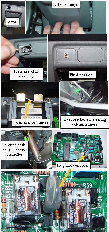
The Insight has three knock out inserts above the small pull out storage compartment (coin pocket) on the lower left of the dash.
Use a small flat blade screwdriver to pry out one of the inserts. The wire must be routed behind the metal spring clips that hold the door open, and over the brace and steering wheel harness(to keep it up and off your feet). The final attachment is a single twist around the center console upright column, and maybe a bit of black tape to hold it. Finally we plug it into the MIMA controller, and are ready to really do MIMA.