|
5. Installing the rear connections |  | | | Dont let the magic smoke out |
OK, just trying to get your attention with the photo.
If the directions are followed, and you get someone to double check your work, MIMA will work the first shot with no problems, just like it has for the other 34 people that have been enjoying MIMA.
One of the most important things to keep in mind while doing this install procedure is that one wire in the wrong place on a connector could damage the cars electronics and make the car inoperable. You can mix things up all day while the connectors are in your hand and the car off,with no damage to anything, but just one turn of the key with MCM, ECM, or BCM connections plugged into the respective computers in the wrong place, and POOF, the magic smoke comes out somewhere, and you could be looking at several thousands of dollars in damaged computers. Check and have someone else double check each connection, and you will not have any problems. A very easy thing to do is to pull out a pin, and then when putting in the MIMA T pin, to put it back in in the empty pin position right next to it. Thats why you need to use the photo as your guide, and double check or have someone else check your work before the big smoke test, not after it.
|
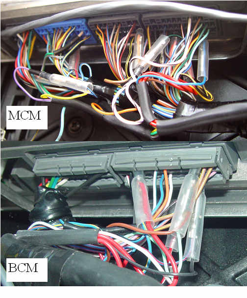
Pulling the connectors and securing the harness
|  | | | pop the connectors and attach the harnesses |
In all of the installs that I have done, it always seemed that the release pin on the MCM and BCM computers connectors were positioned so you had to have double jointed wrist and fingers to make them release while prying out the connectors.
I finally have found the most natural and easiest position for getting those babies out.
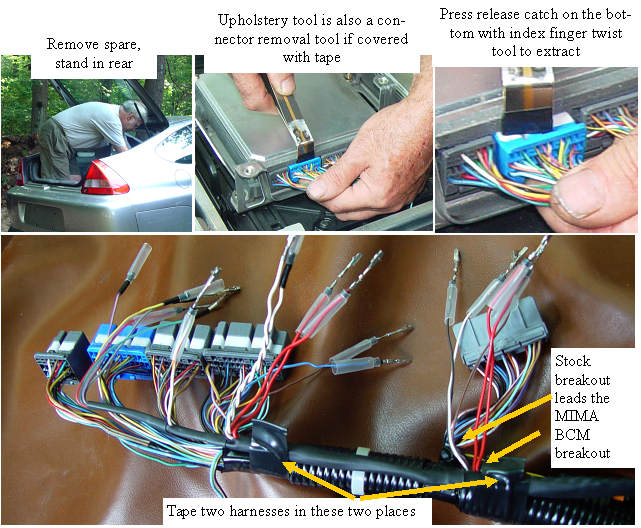
Remove the spare tire, and stand in the tire well. Bend over and reach your left index finger over the wires, and onto the release catch. A simple twist of the tool, and the connector is out.
The relative position of the breakouts on the stock harness and the MIMA harness wants to place the stock BCM breakout about 1/2 " in the lead position compared to the MIMA breakout. A couple of wraps of tape in the two areas indicated, and you are ready to pinpop.
I highly recomend that you carefully read about how the connectors work and the best way to use the tools.
Connector instructions
|
Unlocking the pins on the BCM connectors
|  | | | BCM pin release |
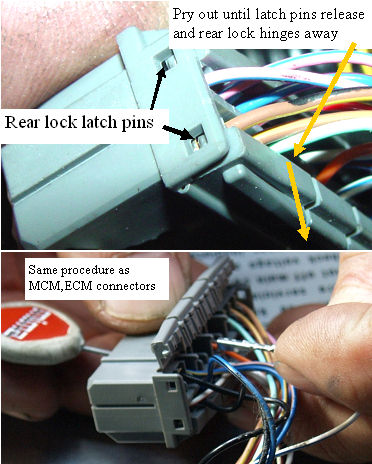
Before you start with the pins, remove the black tape that is covering the BCM wires. This will allow better access to the connector rear which will help a lot.
The "all pin lock" on the BCM connectors is like a hinge. The rear section is pried out until it releases and swings back. This releases the pins on half of the connector. The pins are then individually released by using the pin tool in an identical way as the MCM and ECM connectors. |
BCM connections
|  | | | BCM connections |
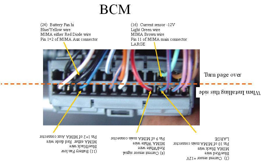
Please note that the two red diode wires in the BCM harness are interchangeable, as are the two on the MCM harness.
Please download and print high res
Download BCM PDF |
Format of pin instructions
Each of the MIMA connections is described with the following naming convention.
This example is from Pin 24 of the BCM connector.
(24)Battery Fan Hi : (24) is the connector pin number, and the function of this pin is to turn on the battery cooling fan to high speed.
Blue/Yellow wire : This is the color of the stock wire going to this pin.
MIMA Red Diode wire: One of the two thick red wires coming out of the BCM breakout of the harness
Pin 1+2 of MIMA Aux connector: The termination point on the MIMA main board.
The BCM connector numbers go right to left starting in the lower right pin. Pin 14 starts back on the top right. |
MCM connections
| 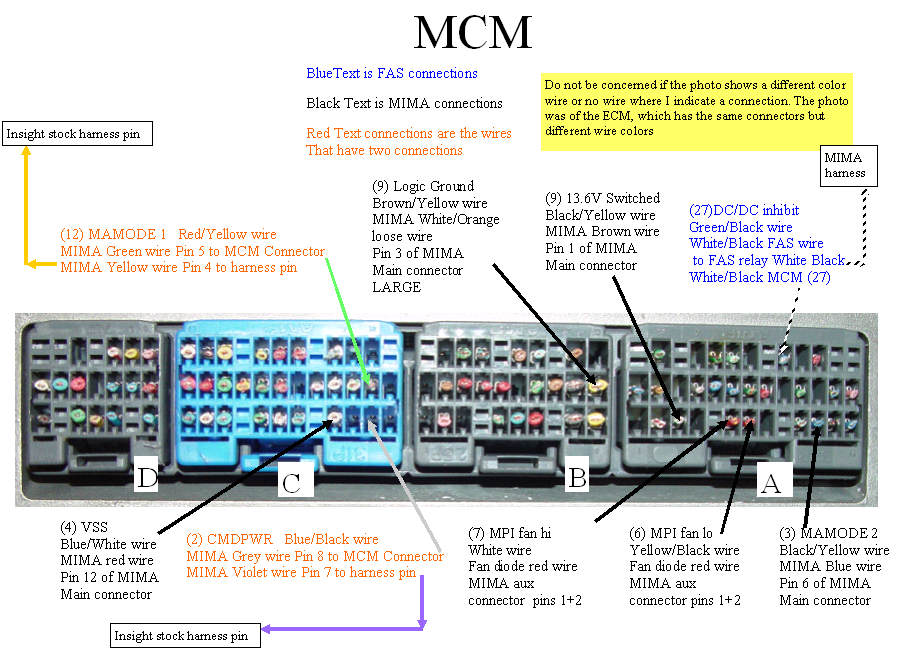 | | | MCM connections |
The MCM photo was actually a photo of the ECM connector which happen to be identical. There is a different color code used on the pins of each so don't look at the color on the drawing, it is not valid, just read the words. You will notice that the descriptions are color coded to distinguish the types of connections.
The BLUE text connections are the two ends of the DC/DC converter enable line that goes to the FAS relay.
The ECM end of the harness is plugged into it self to jumper the DC/DC enable line, for normal stock behavior without the FAS system.
The red text is the two main MIMA control lines into the MCM. Here the naming convention varies a bit.
(12) MAMODE1 Red/Yellow is the same as the other pins.
MIMA Green wire Pin 5 to MCM connector: This means that this green wire and it's terminating connector will plug into the connector in place of the stock pin that was in the pin 12 position.
MIMA Green wire pin 5: This will be a bare female pin with short white wire that connects to the fine green ribbon wire.
MIMA Yellow wire Pin 4 to harness pin: This is a male pin with clear insulation over it and will plug into the cars stock harness pin that used to go to pin 12. The insulation keeps the pins electrically insulated. This yellow wire runs to the main MIMA connector and connects to pin 4.
Download and print the high res PDF.
Download MCM PDF |
Securing the connections
|  | | | How it looks all back together |
Once all of the connections have been made, and have been double or triple checked (remember the smoke!!), we will plug in the connectors, and move to the front connections. |
Installation and introduction: |
|
