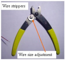
6. Level 1 Install (rear connections)Before we start connecting wires, there are two splicing techniques that will be used here. One is the tap, the other is the splice. A tap is where a wire that runs from one place to another, wants to have another wire connected to it without cutting the wire. This is done with the wire strippers, set correctly for stripping the wire without cutting any strands. The stripper is squeezed down on the wire at the tap location, and is pulled about 1/8 to 1/4" while holding back on the wire. This will bare about 1/4" of the wire by bunching up the insulation.
|
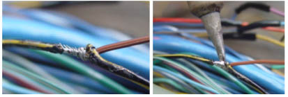
Making the connection
Once the insulation is stripped back, twist the tapping wire around the bare wire, Solder it, being careful not to leave any sharp points sticking out that could pierce the tape and short to another wire. |
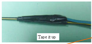
Tape up the connection
Tape up the connection with 2-3 wraps of tape. All taps will be made this way.
|
STST (Strip, Twist, Solder, Tape)
The four splice connections will be made by stripping about 3/16" of the insulation from the two wires, twisting one over the other, then soldering and taping. For the rest of the instructions, the tap or splice connections will be referred to as: STST (Strip, Twist, Solder, Tape)
|
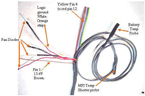
Rear harness
Here is the rear end of the wiring harness once you take the white wire off. |
Rear Car Connectors
The connectors of the MCM and BCM each have a unique shape that will help you to identify the correct pin# for each of the connections. Since the harness is open, you first find the pin, then follow the wire out of the rear of the connector, and confirm that it matches the color indicated for that pin. |
Wiring Protocol
Next, we need to make a series of connections from the wiring harness to your car. There are 15 connections to make,in the rear and the protocol is listed below. It will start with the color of the wire, details about it, and where it needs to go in your car.
Warning: There are two brown wires. The loose one is for power, the other is part of the ribbon cable. If you connect these backwards, smoke will come out, and the car will never be the same again. |
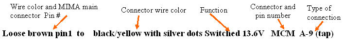
Brown Pin 1 to black/yellow with silver dots Switched 13.6V MCM A-9 (tap)
The Brown wire in that is loose in the harness end taps onto the black wire with a yellow stripe and two silver dots coming from the MCM connector A, pin 9 . STST the connection. This is the main power to the MIMA card.
|
Blue Pin 6 to Black/Yellow MAMODE 2 MCM A-3 (tap)
The Blue wire in the ribbon end taps into the Black with yellow stripe coming from MCM A-3, STST the connection. This is the MIMA signal that controls the availability of assist or charging.
|
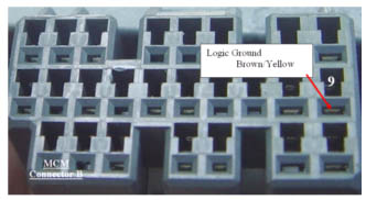
White with orange stripe to Brown/Yellow with silver dots wire Logic ground MCM B-9 (tap)
The heavy orange wire with white stripe taps the Brown/Yellow wire coming from MCM B-9
This important connection taps into the Logic ground used as a reference by the MIMA board, and the MCM and ECM for the main MIMA signals. STST the connection.
|
Level 1 Installation: |