2. DisassemblyPreparation:
The following tools and equipment will be needed to complete this installation:
Good pair of small wire cutters
Wire stripper
Roll of black electrical tape
Metric wrenches
#2 Phillip screwdriver
Wide flat blade screwdriver
Torque driver #T30
Soldering iron with fine tip
Fine solder
Digital multimeter, even a cheapo $10 radio shack one will be good enough.
Wire fish will be included in the kit.
The built harness connects to the rear harness of the car, with 15 connections.
The wiring diagram can be downloaded from the downloads page.
|
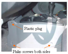
Shift console removal
Unscrew the shift knob by turning it counter clockwise until it is off the screw.
Remove the four screws (2 on each side) at the corners of the shift console cover, and pop out the plastic plugs. The shift console cover should now lift right out of the car. The plugs are in there pretty good, so pry carefully with a wide blade flat screwdriver. If the plug breaks, you will have to get a replacement from your Honda parts department. |
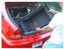
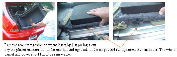
Remove rear storage compartment
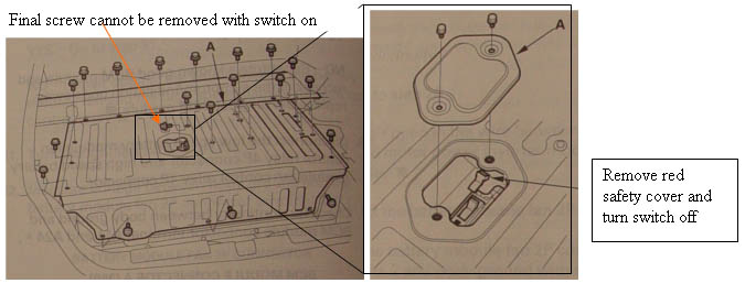
Danger you are about to open the High Voltage area of the car. Always leave the battery switch off while the cover is removed. |
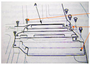
Remove all the torq and 10mm bolts from the rear covers.
|
Continued...
Once all of the screws are removed, the switch turned off, and the final screw removed, you must also remove the small aluminum cover to the right (from rear) of the electronics area.
This cover has a variety of different bolts and screws the plastic screws on the front look like standard Philips, but may not unscrew, and will need to be pried out. There are two bolts on the back, one is hidden by the carpeting. Finally the plastic push plugs will need to be pried out. Once this panel is out, the big cover should easily lift out.
|
Level 1 Installation: |