11. Level 1 Check first power upTurn off the car. Unplug the test connector. You will now be turning on the MIMA system for the first time. Since I have tested the cards here, there should not be any issues with the card, unless something happened during shipping, But we will check out the system carefully without making any assumptions. The joystick , the display, the Main ribbon connector, and the power/fan connectors will be connected at this time.We will leave the MIMA disable switch for later, so any errors will not cause unexpected MIMA activation.
The new system controller boards have shrouded keyed headers, so it is not possible to plug in the connectors backwards.
|
Other connections
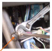
Connect the white wire from the shift console end of the harness to the cars metal chassis, to complete the grounding of the power /fan control circuit.
Everything should now be connected,except the ECM wires, and the MIMA bypass connector. We are ready for the power up test. Whenever powering up a board or system for the first time, the most important thing to watch for is shorted power supplies. This is especially true with MIMA as we use the +12V and 12V from the battery sensor to power our opto coupler input. The rest of the system runs off of the 13.6V main power that has been regulated to 5V. Most modern power supplies can take a shorted condition for a short time without permanent damage, so we will quickly confirm the main 5V power supply first, then turn off the system, reconnect our probes to the +12V and 12V and turn the system back on again to confirm those power supplies.
|
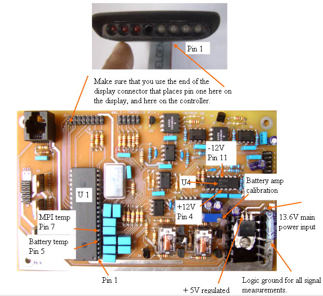
Main Controller test points
|
Test 13.6V supply
Negative probe of your DVM to logic ground. Positive lead to + lead of input filter cap. Should be~ 13.6 with the car running.
|
Test 5V
Connect the negative probe of your DVM to the negative lead of the Input power filter capacitor, or Logic ground. The positive lead will be connected to the left most lead of the regulator IC. Turn on the ignition, but it is not necessary to start the car. The regulated 5V should be 5V +- .2V.
|
+ - 12V supply test
I will be asking you to test voltages on IC pins next. You need sharply pointed test probes to do this, as you must pierce the varnish that is coating the board and components. If your test lead slides off the pin, and shorts two pins, the IC could be damaged, so don't try to do this if you have shaky hands.
First measure the -12V on pin 11 of U4. It should measure -12V +- .2V. Then measure the +12V on U4 pin 4, it should measure +12V +- .2V.
If everything checks out to here, start the car.
|
Board operational check
The car should start just as it did with the test connector , with no IMA or other trouble lights, and should work properly. MIMA cannot operate yet as the MIMA disable switch has not been plugged in.
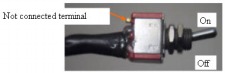
If all power supplies look good to this point, turn off the car, and connect the disable switch, making sure the switch is turned on.
|
Level 1 Installation: |