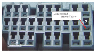
White with orange stripe to Brown/Yellow with silver dots wire Logic ground MCM B-9 (tap)
The heavy orange wire with white stripe taps the Brown/Yellow wire coming from MCM B-9
This important connection taps into the Logic ground used as a reference by the MIMA board, and the MCM and ECM for the main MIMA signals. STST the connection.
|
|