The ECM is in a bad place to work, right under the passenger's feet. To remove the ECM so we can get at the connection points, is no small task, but with care, and patience, should go smoothly.
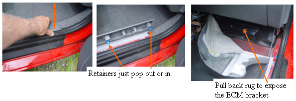
We start by removing the plastic cover over the door jamb, by pulling straight up, so the plastic clips pop out of the holes in the jamb. Then pop the upholstery rivet on the top side of the rug with the provided tool. Remove the plastic rivets that hold the rug under the door, and fold the rug and plastic bracket out of the way.
Getting the ECM separated from the bracket
getting the ECM loose
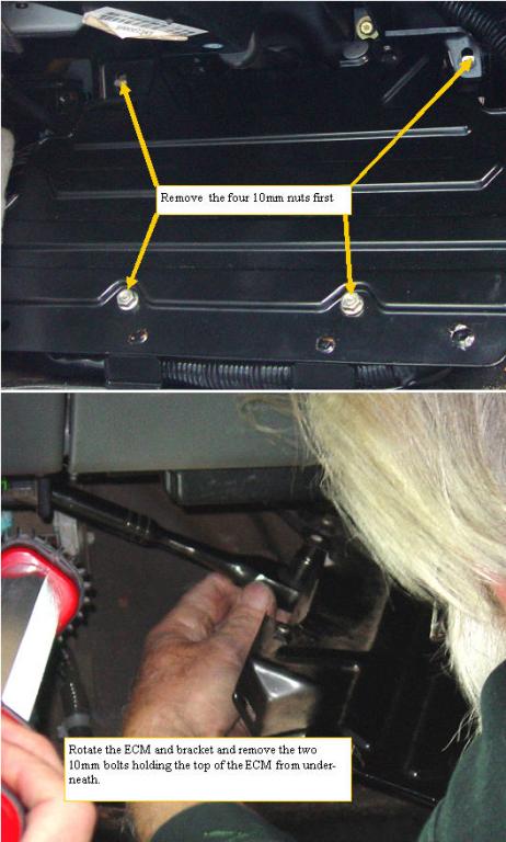
Remove the two 10mm nuts at the top, and the two 10 mm nuts at the bottom of the ECM bracket. Lift the bottom of the bracket up and out, and rotate the assembly counter clockwise, to get at the final two 10 mm bolts that hold the ECM to the bracket from underneath. Be very careful not to stress or break any of the wires, this assembly should rotate with little strain on the harness if you do it correctly. Remove the last two bolts from underneath that are holding the ECM to the bracket,then remove the bracket. The kick plate will be modified and the top attachment screws left out when we reinstall the ECM and plug in adapter. This ECM wiring is the most difficult step of the whole installation, as the harness is in a bad place to work comfortably. I found it easiest to kneel or sit on a soft cloth just outside the open passenger door while leaning into the car to make the connections.This is much easier with the seat out.
Modifing the bracket to allow room for the plug in adapter
Modifing the ECM cover
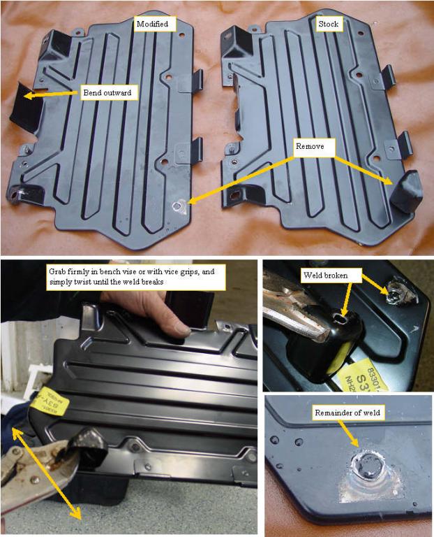
The ECM computer and the wiring harness is tucked under the black metal cover. The harness is held under the cover by a stamped metal piece on the lower right corner. The plug in adapter was made as small as possible, but with it installed, the main ECM harness must be moved out about 1.5 inches, which would put it right under the stamped metal piece. Another issue is that the ECM is screwed to the cover from underneath, which means that one cannot neatly position the harness/plug in adapter/FAS with the ECM in the mounting position, which is the best way to assure that the harness and adapter are properly positioned. I determined that two small modifications to this plate solves all of the problems. The first is to put the stamped metal piece in a vice, or grasp with vice grips, and to rotate the plate by hand. This will rip out the spot weld that attaches the stamped piece, and open up this restriction. The second modification involves simply bending the metal tab that sits over the ECM top slightly outward to allow the cover to be passed over the ECM in its final mounting position. A bench vise will be the easiest as it will more firmly grab the tab that must be removed. The modified cover will be as strong and offer the same protection to the ECM as the stock cover.
Removing the ECM breakout tape
removing the black tape
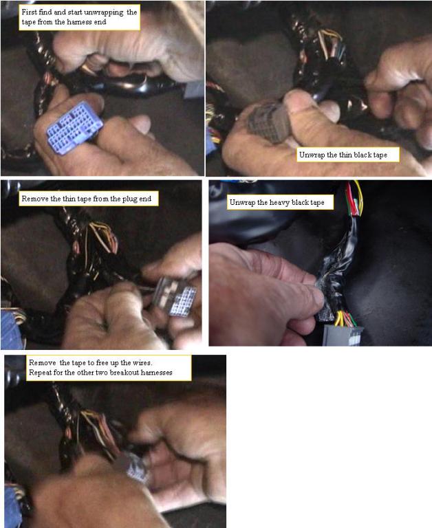
The three breakouts from the ECM harness are covered with standard black tape and some very heavy black tape. This makes the harness very inflexible, and if forced, could cause a wire to break internally which could be a big and difficult to find problem. The harness will be much easier to re form as required for unstressed installation with the ECM plug in adapter if the black covering is removed. This covering can be removed without sharp scissors or knifes if you patiently find where the last wrap of black tape is, and simply start unwrapping it from there. The plug end and the harness end of each covering is wrapped separately on some cars, and on others it is wrapped from the plug end all the way to the harness end, so look for the tape end on the harness end, and start unwrapping from there. Once the three breakouts are unwrapped, the loose wires can be easily moved without stress.
Attaching the ECM plug in adapter
ECM with wires dressed ready for kick panel
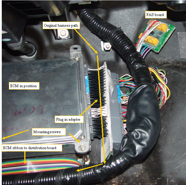
The ECM plug in adapter is first plugged into the ECM, then the 4 harness plugs are plugged into the plug in adapter. The main harness is lifted, and the ECM is placed on the two bottom mounting studs. The loose harness wires are gently redirected under the main body of the harness, and the main harness is pressed down on top. The main body of the harness is then routed to either the left or right side if the top right stud, depending on which side lets the harness sit with the minimal stress. Lift the harness and plug in the ECM to distribution board ribbon, and route it as shown in the video. This only should take a few minutes. While removing this covering is exposing the harness wires, which would seem to make them more vulnerable, they are well protected by the black cover and the rubber coated floor pan.
If the FAS system is attached, the FAS will be passed under the main harness,as shown and located to the upper right of the ECM.
The ECM mounting screws that we had to take out from underneath, are not installed when we put the cover back on to allow cover install and removal without requiring movement of the ECM /plug in adapter and harness, since we have just routed them so nicely. The cover is reattached using the four mounting nuts.
routing the ECM ribbon to the distribution board
Routing the ECM ribbons
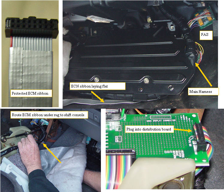
The ECM Plug in adapter is connected to the MIMA distribution board with a 16 conductor ribbon. Because the ribbon is in contact with the rug and floor pan, we covered the ribbon with duct tape to give the ribbon more abrasion protection. The rug is lifted, and the ribbon is gently routed to the rug cutout in the front of the shift console, under the distribution board. The ribbon wants to sit flat on the floor pan and as it passes up the the shift console. The ECM side will be plugged into the 16 pin header on the ECM plug in board, and the other end to the ECM header on the right of the distribution board. Once this is connected and the wires dressed, the rug can be placed back in position.