|
5. Mounting the MIMA system in the car. | 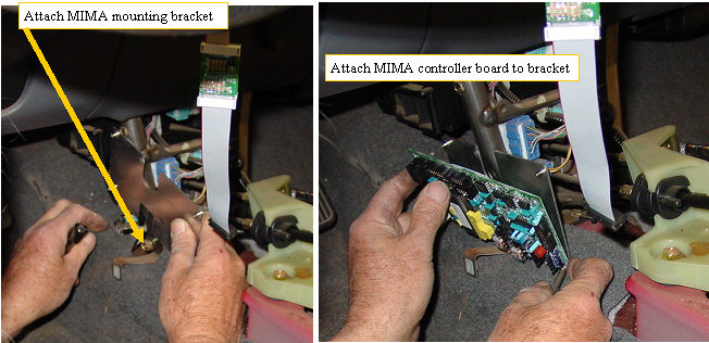 | | | Mounting the controller |
The mounting bracket for MIMA is mounted to the left pillar on the front of the shift console using the bolt that is already there. The board must be removed from the bracket prior to mounting the bracket.
The upright steel tube will protrude through the notch in the bracket. The rear of the MIMA controller has a protective fish paper shield to prevent shorting of the board to the tube.
Loosen the bolt, slide the bracket behind the bolt head and the washer, and down as far as possible, then tighten the bolt. Remount the card to the bracket, and bend the board/bracket slightly away from the upright so the upright just clears the fishpaper.
|
Running the DB-25 under the rug
|  | | | Running the DB-25 to the distribution board |
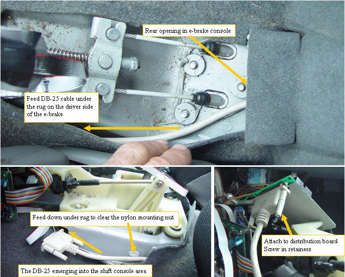
The DB-25 cable that we just ran from the back will be routed on the driver side of the e-brake, under the rug, and into the shift console. Be careful to route the body of the cable down into the rug where it first emerges, so it does not interfere with the shift console mounting screws. The connector is plugged into the distribution board, and the two thumb scret retainers are tightened to hold it in place. The distribution board is laid into the space between the shift mechanism and the front wire harness that is mounted to the shift console front upright tubes. The db-25 will sit right behind the MIMA mounting bracket. |
The distribution board
|  | | | Pluging in the cables |
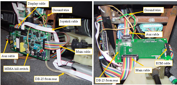
The new plug in system uses a distribution card to make the MIMA controller connections to the ECM, and MCM.
This card sits in the gap between the shift mechanism and the front of the shift console. The green wire from the distribution card will connect to the metal brace as shown. The MIMA Main and Aux cables will connect to the distribution card as shown. The DB-25 that comes from the MCM plug in adapter connects underneath the distribution card. And finally the 16 conductor duct tape protected ribbon cable from the ECM plugs into the right side of the distribution card. |
Mounting the MIMA kill switch
|  | | | Mounting the kill sw |
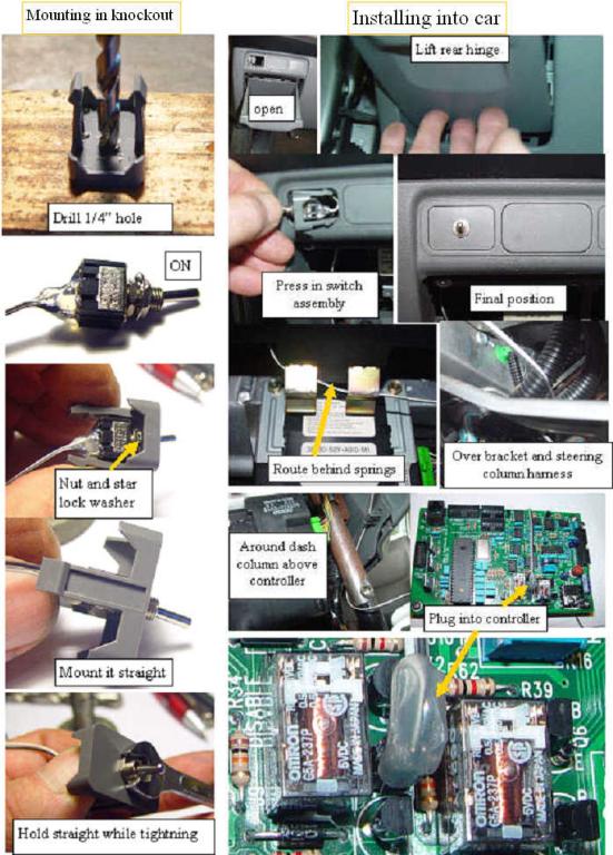
The MIMA system is designed to allow manual control of the assist and regen functions. If you need to disable this control, just flip the MIMA kill switch and the car reverts back to standard IMA and the MIMA card will not cause assist or regen no matter what the MIMA card tries to do. If someone that is not familiar with MIMA must drive, this is a simple way to disable the joysticks.
The switch can be mounted in one of the three knock outs above the small coin holder to the left of the steering wheel. Simply pop out the knockout by prying out with a knife. Drill a 1/4" hole in the center, mount the switch, run the wire, and plug into the kill switch connector on the MIMA card. |
The Kill sw socket
| 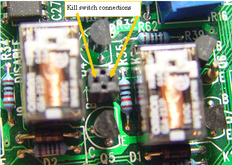 | | | Make sure to plug in the kill switch here |
It is difficult to see the tiny two pin connector on the MIMA controller board that the kill switch plugs into. This is where the pins go. If the kill switch is not plugged in correctly, or is turned off, MIMA will not be able to control the IMA. |
Installation and introduction: |
|
