|
4. Installing the rear connections | 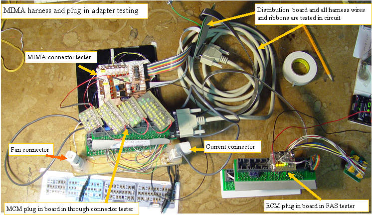 | | | everything is tested together |
When I test the plug in adapters here, I confirm that all of the wires pass from the 104 pin header to the correct position on the related plug.I inspect all solder joints for mechanical and electrical integrity, and confirm that the MIMA signals are completed to the correct tie points.I confirm that there are no wires crossed or shorted. This lengthy inspection and test should eliminate any possibility of wiring errors, and is one of the biggest advantages over the previous MIMA harnesses, as no electrical testing is required in the car, and it is impossible to incorrectly wire the system.Thus we keep the Magic Smoke in place and do not let it out.
|
Pulling the connectors
|  | | | removing the connectors |
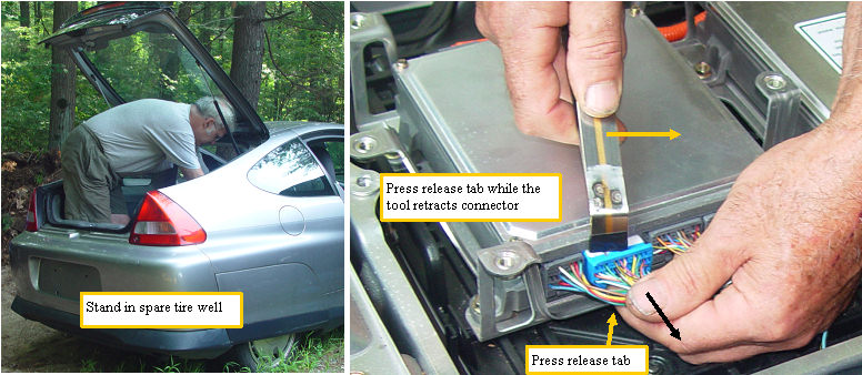
In all of the installs that I have done, it always seemed that the release pin on the MCM computer connectors were positioned so you had to have double jointed wrist and fingers to make them release while prying out the connectors.
I finally have found the most natural and easiest position for getting those babies out.
Remove the spare tire, and stand in the tire well. Bend over and reach your left index finger over the wires, and onto the release catch. A simple twist of the tool, and the connector is out.
If your MCM connectors have never been removed, they can be quite tight. The MIMA upholstery tool also works nicely to pry out the connectors, but only if the release tab has been fully released.
|
Plugging in the MCM adapter
|  | | | Rear MIMA connectons |
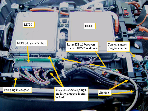
The MCM plugin adapter is plugged in between the stock harness and the MCM computer. Make sure the plugs are fully seated and locked.The fan plug in adapter and the current sensor plug in adapters are simply plugged in between the stock harness and the mating plug.
The adapter uses amp tyco sockets on the slightly larger pins in the stock female socket. If the adapter does not easily plug in,do not force it,the pins may simply not line up exactly with the sockets in the plug. Simply pull the plug in adapter back out and try again at a slightly different lead in angle. Once the pins start into the connector the plug in adapter should fully seat into the socket and lock into place. The stock connector is then plugged into the adapter to complete the circuit. |
Notching the MPI foam
|  | | | Cutting some clearance for the current plug in adapter |
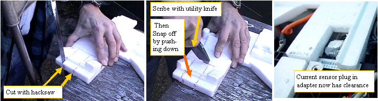
The MIMA current sensor plug in adapter sticks up a bit over the rest of that area of the current board. We must notch the foam to allow clearance. A hacksaw works nicely for the long cuts, and the utility knife will scribe a deep line for the short cut. simply lift the foam when it is cut and scribed, and press down on the piece of foam we want to remove and it will just snap off. |
MPI thermal probe
| 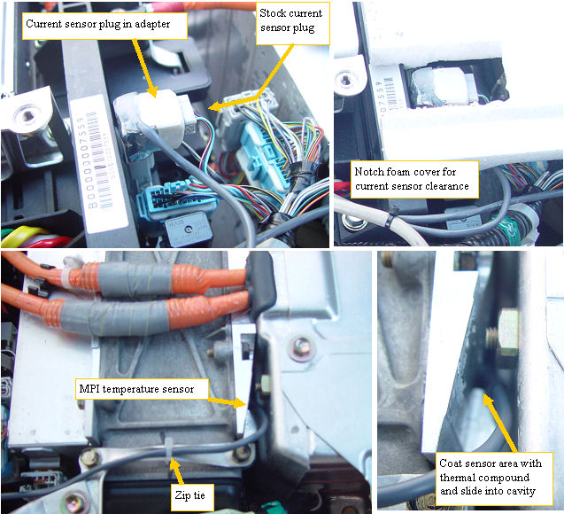 | | | Current plug in adapter and MPI thermal probe |
The current sensor different view.
The MPI thermal probe is coated with a dab of thermal compound, and slid into the small cavity in the MPI heatsink. |
Battery fan removal
|  | | | grab the clips so they don't rip out |
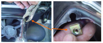
The battery temperature probe will be installed inside the battery pack. First we need to remove the fan by removing the four mounting screws. The metal clips that the screws thread into usually must be held with vicegrips so they do not rip out when the screws are first broken loose. |
insert the battery probe
|  | | | Insert probe and remount fan |
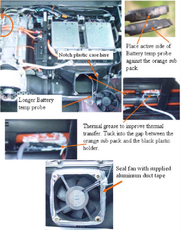
The fan enclosure will need to be notched to allow free passage of the thermal probe. The probe is coated with a dab of the thermal compound on the active side, and is inserted between the black plastic battery retainer and the battery with the thermal probe active side toward the batteries. The probe wires are zip tied to the battery wire, and the fan is remounted. Finally seal the gap around the fan to make the fan more efficient at drawing air through the pack.
The rear install is now finished. Leave everything open until we do the powerup test. |
Installation and introduction: |
|
