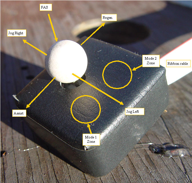
MIMA uses a custom dual axis joystick with two mode switches and a central joystick switch to control the system. The joystick board is covered with a leather cover, and has a long ribbon wire to connect it to the main MIMA controller.This small joystick module can be mounted in many places, so I do not supply a specific mount for the assembly. The system can be calibrated to use two parallel joystick assemblies, so even more flexibility is available. I supply some two part epoxy putty which can be used to form the interface between the joystick assembly and any underling surface. I will show how to mount the two sticks to the two most common areas. The shift knob and the E-brake lever.
The leather joystick
Leather joystick
The leather covered joystick has two hidden switches just below the leather surface. To activate them, one simply presses on the leather in the appropriate zones. This cover protects the circuits, keeps out dust, helps avoid false switch activation, and gives the joystick a more finished look.
Mounting to the e-brake
E-brake joystick
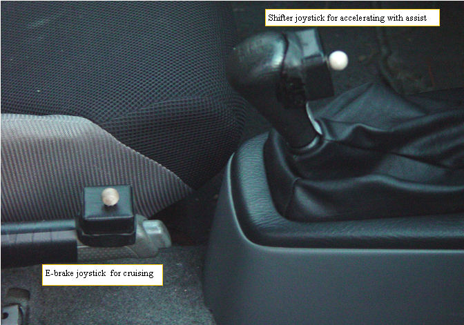
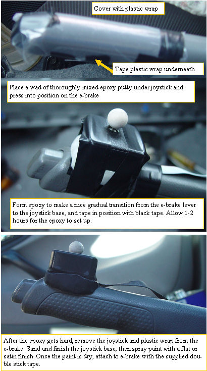
The e-brake lever is a nice place for one of the joysticks. It sits by your side, and is easily accessible with your right thumb. The round e-brake lever is covered with saran wrap or other plastic wrap. The material is tightly taped to the brake lever with masking or black tape on the bottom side.The epoxy putty that I supplied should be divided into three equal amounts of each of the two parts. Mix up one of the divided A and B epoxys. Mix it thoroughly until it is of uniform color. Form it into a square that fits nicely under the joystick. Press the joystick into the epoxy over the e-brake area that you want to mount it to. Once it is fully seated, form the epoxy to make a nice interface from the joystick to the e-brake lever. Using black tape, tape the joystick to the e-brake lever, and let it sit for several hours to set up. When the epoxy has fully cured,(24Hours), sand and paint the epoxy with a satin or flat black paint and let dry. It is best not to paint the mounting surface so the double stick will adhere better. Because we are depending on double stick to hold the joysticks and display in position, it is very important that the surface that the doublestick will stick to is clean and free of oil or wax. I recommend that you wipe the dash where the display will mount, the e-brake lever, and shift lever where the joysticks will mount with 99% pure alcohol, to remove any oil or wax. When the paint is dry, apply two strips of the double stick mounting tape, and stick it in position on the e-brake. The ribbon can be stuck down to the e-brake shaft with more doublestick between the ribbon and the shaft.(sorry I forgot to include enough for that) The ribbon is routed under the rug after you place a layer of duct tape over the part that will be in contact with the floor pan as it passes next to the DB-25 to the shift console.
Mounting the shift knob joystick
Mounting to shift lever
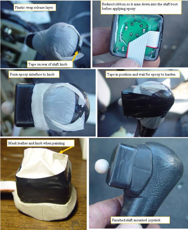
Another nice place for a joystick is on the shift knob. This position allows MIMA activation and control while your right hand is on the shift lever, for regen when downshifting, and assist when accelerating. The procedure is similar to the e-brake mount, and has the additional advantage that it can be mounted indoors once the shift knob is removed. Cover knob with taped on plastic wrap,mix epoxy and place wad on joystick base. Note: The e-brake mounted joystick will give assist and regen when moved in the same directions relative to the switch zones as the e-brake joystick. When deciding which direction compared to the shift lever you would like assist and regen to activate, you may want to take a few days to play with different directions and positions for this joystick by taping the joystick onto the knob with black tape and no epoxy until you find just the right position and angle works best for you. The ribbon can be redirected to come out the bottom no mater which direction you chose. After you determine the best position, again put a square of mixed epoxy putty under the joystick and form a smooth interface to the shift knob and tape while setting up. After the epoxy has set up, do not mount the joystick to the shift knob yet, as we must route the wire through the shift boot.
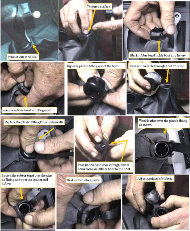
Getting the ribbon and joystick connector through the shift boot
Feeding the joystick wire through the shift boot
Ok this is another place we test your manual dexterity. To get the joystick wire to neatly and safely pass through the shift boot, and still allow the shift knob to be screwed in or out was a challenging problem. A careful look at the small plastic fitting right at the top of the leather shift boot will show that it is textured on the knob side and is larger and smooth on the inside where it is inside the boot. A look from underneath the boot will show that a black rubber band is holding the leather into the groove in the plastic fitting. We will remove that rubber band and then push the plastic fitting through to the inside, and temporarily remove it. We pass the joystick ribbon into the boot from the outside, making sure that we have rotated the joystick to the correct mounting position relative to the boot.We put the plastic fitting back into the boot, and get it back into the proper relationship with the leather. The ribbon connector is passed through the rubber band, and the band is put back over the leather, fixture, and ribbon. Now the whole shift console is ready to be reinstalled, and after installing, the shift knob is screwed back in, and the shift joystick is stuck to the shift lever with double stick. The excess ribbon is folded up and tucked just to the front of the shift mechanism.