The end of the Plug and Play MIMA, and MIMA2
MIMA introduction
MIMA Operation
MIMA Users Page
Installing MIMA with The Plug and Play harness
Installation and introduction
1. Disassembly
2. Gaining access to the opening behind the seats
3. Threading the DB-25 to the front
4. Installing the rear connections
5. Mounting the MIMA system in the car.
6. Accessing and connecting to the ECM
7. Installing the MIMA joysticks
8. Mounting the display
epoxy forming and display painting
feeding the display PC board and connector through the bezel
9. First powerup
10. The first MIMA operational test
Installing MIMA in a RHD Insight
FAQ
Installing MIMA with the pin replacement harness
software
The MIMA Joystick
The MIMA Display
The FAS system
DIY MIMA L
Cable impedance problem with last MIMA systems.
Learning to drive with MIMA
Hardwired Harness
Theory of Operation

8. Mounting the display

8. Mounting the display
Mounting the display

The mounting of the new low profile display is very simple. The display is designed to be pressed into the gap between the steering column bezel and the dash bezel.
The problem that had to be overcome was that every car has a different width gap, and some have a rather large mismatch in height between the two bezels. The display angle should be adjusted so the top is invisible to your normal viewing height. The display should also be positioned side to side so that the central led is directly under the C in the FCD lettering under the bargraph.


epoxy forming and display painting
mounting display
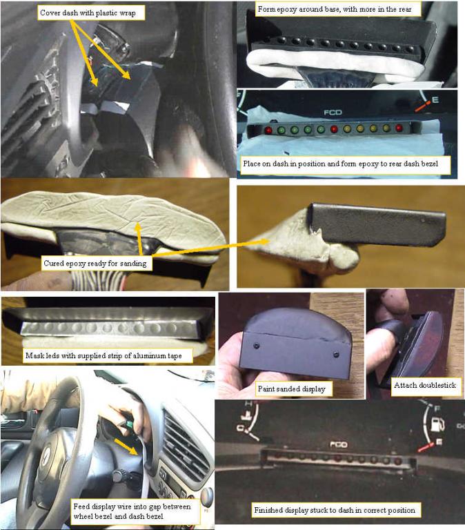
First we will cover both the front and rear surfaces of the dash and steering column bezel so the epoxy does not discolor or stick to it.
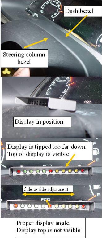
The two pieces of plastic are held in position with black tape.Next we mix some epoxy putty, and form it into two long round strips a thin one is placed below the front surface, and a thicker one on the back. The back piece is pressed against the rear of the display. The display is put in position in the crack, and centered on the FCD display. Tip the display so that in your normal driving position, you can see the FCD bargraph, and form the epoxy to hold it in this angle while fitting the contour of the underling dash.
After the epoxy sets up, sand and shape the epoxy so it looks nice.
Place some of the red backed doublestick tape on the rear area of the display epoxy and cut the doublestick so it matches the sanded display base, but do not remove the backing.Use the supplied strip of aluminum tape as an led mask,and then paint the display and epoxy flat or satin finished black. When the paint is dry, peel off the led mask, and the doublestick backing to expose the sticky material.Pass the display ribbon through the slot, and stick it to the dash so the center red led is exactly in line with the C in the FCD.Once you are happy with the position, press the doublestick onto the dash, and your display is mounted.
feeding the display PC board and connector through the bezel
feeding display wire through bezels
The bottom of the ribbon cable needs to be fed into the back of the dash. The dash material is quite flexible, and I have found that simply pulling out on the center of the bottom bezel will open up the gap so the display pc board and connector can be easily passed through.
Installation and introduction:
1. Disassembly
2. Gaining access to the opening behind the seats
3. Threading the DB-25 to the front
4. Installing the rear connections
5. Mounting the MIMA system in the car.
6. Accessing and connecting to the ECM
7. Installing the MIMA joysticks
8. Mounting the display
9. First powerup
10. The first MIMA operational test
Installing MIMA in a RHD Insight