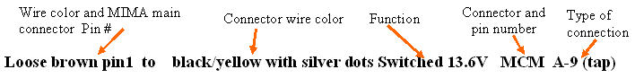
The end of the Plug and Play MIMA, and MIMA2
MIMA introduction
MIMA Operation
MIMA Users Page
Installing MIMA with The Plug and Play harness
FAQ
Installing MIMA with the pin replacement harness
software
The MIMA Joystick
The MIMA Display
The FAS system
DIY MIMA L
Cable impedance problem with last MIMA systems.
Learning to drive with MIMA
Hardwired Harness
Level 1 Installation
2. Disassembly
3. Thread the Harness
4. Threading the Harness, Cont'
5. Opening the Harness
6. Level 1 Install (rear connections)
Making the connection
Tape up the connection
STST (Strip, Twist, Solder, Tape)
Rear harness
Rear Car Connectors
Wiring Protocol
Brown Pin 1 to black/yellow with silver dots Switched 13.6V MCM A-9 (tap)
Blue Pin 6 to Black/Yellow MAMODE 2 MCM A-3 (tap)
White with orange stripe to Brown/Yellow with silver dots wire Logic ground MCM B-9 (tap)
7. Fan Diodes Install
8. Battery Amp Monitor Rear Connections
9. Mounting the MIMA system in the car.
10. Level One wiring test.
11. Level 1 Check first power up
12. The first MIMA operational test
13. Testing the fan control wiring
14. Confirming temp probe and fan control operation
Level 2 install
Theory of Operation

Wiring Protocol

Next, we need to make a series of connections from the wiring harness to your car. There are 15 connections to make,in the rear and the protocol is listed below. It will start with the color of the wire, details about it, and where it needs to go in your car.

Warning: There are two brown wires. The loose one is for power, the other is part of the ribbon cable. If you connect these backwards, smoke will come out, and the car will never be the same again.

Wiring Protocol