The end of the Plug and Play MIMA, and MIMA2
MIMA introduction
MIMA Operation
MIMA Users Page
Installing MIMA with The Plug and Play harness
FAQ
Installing MIMA with the pin replacement harness
software
The MIMA Joystick
The MIMA Display
The FAS system
DIY MIMA L
Cable impedance problem with last MIMA systems.
Learning to drive with MIMA
Hardwired Harness
Level 1 Installation
2. Disassembly
3. Thread the Harness
4. Threading the Harness, Cont'
5. Opening the Harness
6. Level 1 Install (rear connections)
7. Fan Diodes Install
8. Battery Amp Monitor Rear Connections
9. Mounting the MIMA system in the car.
10. Level One wiring test.
11. Level 1 Check first power up
12. The first MIMA operational test
Ammeter zero level
Jog the calibration
13. Testing the fan control wiring
14. Confirming temp probe and fan control operation
Level 2 install
Theory of Operation

Jog the calibration

Jog the calibration
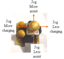
To jog the calibration, you must be moving over 19 MPH, and be in PIMA (mode 2). A single jog, is moving the joystick to the desired position, then allowing it to return to center. Each time you do this, you change the setpoint in that direction by 2 units out of a total of 118. Future software will detect the lack of the MAP signal , and will disable the PIMA mode until it sees a correct Map signal.

Pick up any loose tools, and make sure everything in back is secure, and go for your first MIMA ride. But don't go too far, as the real fun comes with the PIMA mode, and you still have 6 more wires to connect, and the temperature probes to test and install.