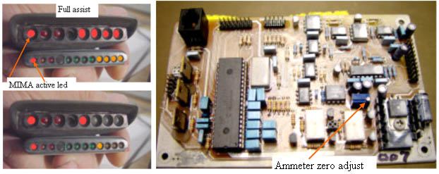
Ammeter zero level
I have approximately adjusted the ammeter zero level on your card on my car, but each car is slightly different, so we will now zero the ammeter. First make sure that no fans or A/C, lights, radio, or other loads are operating. Quickly tap the mode 1 button on the joystick. The mode 1 active led should light. This mode disables background charging. All other leds should be out, but one assist or one charge led may be on.
Adjust the Ammeter zero adjustment potentiometer until all of the amp leds go out. This is a sensitive adjustment, so turn slowly. If more red/amber leds come on while you adjust, you are going the wrong way.
Since we have not installed the map or throttle position signals, PIMA will not operate correctly. The map signal will be 0 V, so the system will try to give full charging. To fix this, while driving, activate PIMA by taping the mode 2 switch. Full charging will occur. Jog the charge calibrate joystick repeatedly to the lower charge position, until the charge leds go out. (you could also set some level of charge, and use this as an adjustable background charge control)
|
 | |
|
|
