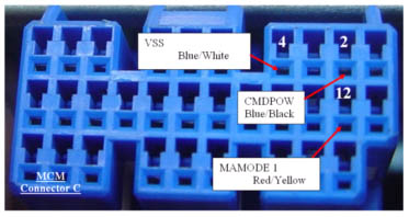
Yellow Pin 4 to Red/Yellow wire MAMODE 1 ECM side (Splice)Green Pin 5 to MCM side of wire(splice)The first of our spliced connections. The wire is cut at the splice point. The end of the wire that goes to the MCM-C connector will splice with the green wire from the ribbon. The end of the wire that leads to the front of the car will splice with this yellow wire in the ribbon. STST the connections.
This signal is a PWM 20khz 50% duty cycle square wave when in charge enable mode, and shifts to a 25% duty cycle when full assist is enabled. It is one of the two signals that MIMA replaces when MIMA is active.
|
|