The coupling
|
 | |
|
Drive shaft is coupled to clutch disk
|
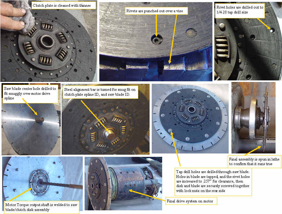
The tranny has one size spline, and the motor had a slightly smaller spline, so rather than spend a lot of time and money trying to find an adapter, I decided to use the clutch plate which already mates to the tranny shaft, and adapt it to the motor output shaft, using a steel disk. While a 10" to 12" saw blade would do the same job, I found some larger blade blanks that I had been given by a friend, and decided to use that.I punched out 10 of the outer rivets on the clutch plates, opened the holes to the tap drill size for 1/4-28 screws.
I turned a snug fitting steel alignment shaft that fit on the ID of both the clutch disk spline and the saw blade ID. This forced the two disk to be centered on each other. I clamped the two disk together, and drilled the tap drill holes through the blade. The blade holes were tapped to 1/4-28, and the clutch disk holes were opened to 1/4". The motor output shaft was welded to the saw blade, and the clutch plate was screwed to the saw blade to make the final adapter. The assembly was spun in a lathe to confirm that it runs true. Now the delicate and critical final step of mounting the motor to the bell housing exactly concentric with the tranny output shaft. Both the tranny output shaft, and the motor output have some degree of shaft misalignment compensation which should help.
|
|
