|  | |
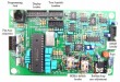
The MIMA system is unique in the world, as it directly ties into the cars control and sensor system with 21 connections.
The new install technique was designed to make the system a plug in that could be removed if necessary in only a few hours.
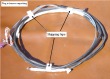
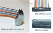
The new install uses custom made adapters. The adapters come it several types,Male, Female, T, and in small and large versions of both. I use the exact pins and receptacles that are used in the stock connectors.
The MIMA pin adapters are not a socket and plug with a double locked pin and receptacle, but a naked pin and receptacle with no lock.Therefore it will not resist unplugging if tugged.
If the stock harness receptacle pulls out of the small male pin, when you tuck the harness and ECM back in, it will cause a check engine light.
I recently had a gentleman install his MIMA here, and the car would not start, we jumped started it and when it turned over it ran fine. The clutch wire of the FAS had pulled out of the rear of the MIMA pin adapter, and the ECM would not allow a start without the clutch signal.
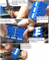
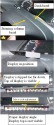
I have been using a bit of black tape on both sides of the MIMA flying pins to assure that they stays together when the harness is tucked back in.
Another note about the black tape on the original harness. It is only black tape, don't be afraid of removing some of it if the additional freedom of the wires will allow better final wire dress. The black heavy tape they have on the ECM connector should also be removed for 2" from the connector rear to allow you to gently form the new wire bundle for best strain relief.
The final step of the install is to gently form the bundle of wires on each connector into a bundle like it was, and wrap some black tape over the whole thing, always being mindful of how easy it is to pull out the "T" pins and flying pins.
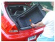
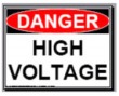
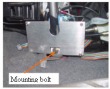
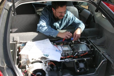
Because of the large number of connections, extreme care must be exercised to assure that all the connections are sound, insulated, connected to the correct points, and are thoroughly tested before connecting the MIMA electronics. While none of the connections are made to the High Voltage Battery or power wires, we will be working on the rear section of the car where those wires are present, and exposed. I would strongly recommend that you do not attempt to install MIMA if you do not have the required skills to do it correctly and with confidence. The car can be damaged, the MIMA circuits can be damaged, you could be electrocuted, or burned. This is not a car stereo install, it goes much further. I am attempting to provide thorough step by step instructions, with many photos to guide both the novice and professional through this installation, And will continue to refine them as I receive feedback from the people doing the first installs.
|