The mounting plate
|
 | |
|
Motor mounted and ready to go
|
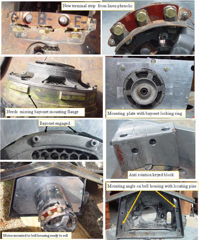
The broken terminal strip was replaced with a new one machined from a piece of linen phenolic that I had. I pressed in large brass nuts, then glued them in with epoxy. The next issue was the strange mounting system. The motor was designed to fit a cast iron mounting flange with a bayonet lock and keyed anti rotation section. I chose an easier to make 1/2 " aluminum plate, and a bayonet ring of just the right thickness so I had to tap it with a hammer to lock it in. A separate steel keyed block was made that bolts to the large aluminum mounting plate. The bell housing looked a bit weak to support the 90 lb motor, so I welded up a complete angle iron bracket to carry the weight.
I clamped the bell housing on my bridgeport table then indicated the round tranny locating hole on the bell housing to center the miller quill on the tranny mounting hole.Then I took the main motor mounting plate and with the indicator got that exactly concentric with the tranny hole. With the plate clamped to the bell housing I drilled two spring pin holes and drove in the spring pins to allow disassembly and re assembly with perfect alignment. I transfered the two 7/16-14 holes to the mounting plate and drilled clearance holes.
The final step was to determine the exact thickness spacer necessary to engage the clutch plate with the tranny spline with about 0.02" clearance between the two shafts.
With some help, the assembly was mounted. Next step battery holder.
|
|
