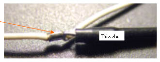
Cut off the bare wire of the diodes, about 1/4" from the end of the heat shrink. Strip back a small amount of the wire insulation, twist the bare wire around the end of the diode, and solder, with no sharp ends, lay the diode next to the wire,then tape over both the diode and the wire. STST all connections. (caution)Diodes can be damaged by excessive heating during soldering, so prepare the diode and wire, and quickly make the solder joint, but make sure the solder flows well into the connection.
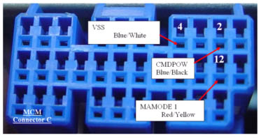
Yellow Pin 4 to Red/Yellow wire MAMODE 1 ECM side (Splice)Green Pin 5 to MCM side of wire(splice) The first of our spliced connections. The wire is cut at the splice point. The end of the wire that goes to the MCM-C connector will splice with the green wire from the ribbon. The end of the wire that leads to the front of the car will splice with this yellow wire in the ribbon. STST the connections.
This signal is a PWM 20khz 50% duty cycle square wave when in charge enable mode, and shifts to a 25% duty cycle when full assist is enabled. It is one of the two signals that MIMA replaces when MIMA is active.
Violet Pin 7 to Blue/Black CMDPWR ECM side (Splice)Gray Pin 8 to MCM side (splice) The second and final splice connections are made to this Blue /Black wire from MCM C-2.The Blue /Black wire is cut at the splice area. The end of the wire that goes to the MCM-C connector will splice with the Ribbon gray wire pin 8. The end of the wire that leads to the front of the car will splice with the Violet Ribbon wire pin7. STST the connections.
This PWM signal is the direct controller of the level of assist and charge. It is a 2khz 50% duty cycle signal when no assist or charge is required, increases to 90% duty cycle when full assist is required, and to 10% duty cycle when full charge is required.
Red Pin 12 to Blue /White VSS MCM C-4 This signal is the pulses that tell the car how far and how fast you are going. The pulses stop when the car stops, and at 100 MPH, the frequency of the pulses is about 110HZ. STST the connection
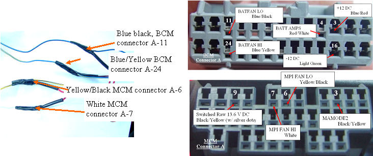
Fan control Diodes (Tap) Fan control diodes are already connected to the red wire in the MIMA harness. The other side of the diodes will be connected to four of the wires in the harness.