MIMA 010K Hypermiler Predrag
|
 | |
I am posting this extensive report in hope that it will clear some of the unknown areas about kit building and installation of MIMA. Added is a comment of my user experience so far.
1. KIT ASSEMBLY
I was reasonably nervous after the decision to build the MIMA from kit, since I have never really done any serious soldering nor electronic assembly before. The amount of time required to put it all together was completely unknown, but here are results now: board itself takes about 4-6 hours, display less than 30 minutes, and harness about 1 hour to complete. The joystick comes assembled, and so do the temperature probes (those resistors are about 1.5 mm in diameter, and I think Mike uses the microscope to put them together!).
The basic principle of soldering electronics is to heat both the board and the component at the same time with a wetted iron tip, and then to introduce some more solder to make the connection. Iron should be removed just at the point when solder is seen to flow down into the board hole. In my experience, the whole iron to component contact never exceeded 2 seconds. If this doesn't work, it is advisable to remove the iron and wait for the component to cool, so not to damage it.
While building the board, it is good to start with resistors, since they are the lowest (stick out the least) and are hard to damage by overheating. Insert the element or a few of them through the board, slightly bend the wires on the other side to prevent them from falling out, flip the board over and solder them all at once, then clip the excess wire close to the board, inspecting that the contact is full, but it doesn't short with anything around. Leave those upright mounted resistors for later, and move on to the next higher component, capacitors. As I can see on www.99mpg.com , Mike has laid out the board building order just fine.
Be careful not to mix up the components that come within the same envelope: a few of them contain resistors that look fairly similar, yet go to the specific contacts on the board! (I managed to screw up 2 times.)
Mike will test the boards and make necessary repairs, but that takes his time and your money!
Display is a piece of cake after the complex board, but pay attention to the diode orientation (it is printed on the board itself!). After taking care of resistors and a transistor, start with soldering the black photo cell, then slip the plastic bezel over it and use it as a holder for led's - cut their wires to exact length and slip them into the bezel holes, then solder all of them to the contact points.
Harness is not hard to do, but do make sure you measure the wire correctly, so not to end up short where it counts later. It is almost worth buying a heat gun to shrink the shrink tubing correctly. I wouldn't be doing this length of tubing over a kitchen stove!
One more thing you should address is joystick and display mounting: after deciding where you want it to go, that epoxy really works in making the case and the mount fit. If you want to conform to any shape in the car (like shifter knob, or dashboard shape for the display), use saran wrap on the car, and let the epoxy harden on it. It is better to start with more material, as it is easy to sand the hardened epoxy down. I tried some double stick tape to mount a joystick on my shifter knob, but found out that hot melt glue works better.
2. INSTALLATION
This is covered on the website, so I won't go into the details. Here are couple of suggestions, though.
Mark the rear cover bolts with the marker on the cover ("H" for hex, etc.). The bolts are all the same except for 2 shorter hex bolts that take care of the breaker switch cover. Remember to also unscrew that small black hex bolt in the breaker compartment without which you cannot remove the cover.
Fishing the harness from the parking brake to the rear could be tricky, but it works with an almost straight piano wire (fed from the rear), which comes out down at the opening behind the brake.
Take a digital photo or make a diagram of the original wiring wrap - so you can restore it to the "factory" appearance later.
Get a good pair of wire strippers! With bad ones, it is easy to cut the wire you just want to tap into! (Well, no problem, as you can still just solder it all up - but that shortens the wire and makes it harder to wrap back.)
Make sure you identify the wire both by the connector position and the color - double check yourself here so you don't have to go back!
In front, do not forget to connect the ground wire with bolt to the car frame (just above where the board is mounted).
Route all the wires neatly along the existing wires where possible.
Make sure the joystick cables don't rub against the shift rods inside the console - if you are mounting joysticks there (as I have mounted them both), tape the ribbon cables to the console housing on the inside, going all the way to the board.
Mount the MIMA kill switch in one of provided switch mounting plates left from the steering wheel. They pop out easily, but the best is to push them from the back. Take out the little drawer there, and "somehow" get your hand into the position to push one of those out. You are allowed to use a tool too. While drilling the little plastic plate, bear in mind that it is quite brittle! Go with the smaller diameter bit first!
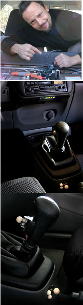
Here are pictures of my controls:
http://predrag.net/mima%20install/p%20dispay&joysticks.jpg
http://predrag.net/mima%20install/p%20joysticks.jpg
3. DRIVING WITH MIMA
Well, it's fun! They don't call them JOYsticks for nothing! But then, you want to talk about this seriously, right? One of the most prudent ability of MIMA is to actually turn off the background charging, and then your car achieves the mileage like when it has a full battery. This amounts to something like 85 mpg at 55 mph, flat road, no wind, in my car. With background charging, it is hard to achieve 65 mpg at 55 mph. What I found myself doing before was trying to keep the battery in top 1/4 range, just to have this kind of mileage! Well, now I can use the whole battery capacity and still get it. Which in turn means that I can go climb a bigger hill and not have my mileage suffer - especially because now I can use more electric assist without pressing the throttle further and increasing gas consumption.
Performance? Well, the electric motor has the torque peak at 1500 rpm, that low. I live on the hill that I had to climb in the first gear. Now I can do it in second, just pull the joystick up and barrel up like a tractor at 1500 - 2000 rpm. With this additional torque, starts from the full stop are quite fun too.
Charging the battery is much easier as well. It is now possible to charge (and that at full 50A!) all the way down to auto stop. I do not use my FAS switch (forced auto stop, by ignition circuit interruption) while coming to stop, but just jam the joystick down, and when I press the clutch when the charging lessens (engine speed around idle), engine goes to auto stop immediately. On the road, I often drive in MIMA active mode, then switch it off into on-demand mode on the slight downhill to charge the battery up without much attention demand.
PIMA is something one would want to use when not in the mood to play with the buttons too much. Basically, we aren't saying that automatic IMA is that bad - as long as we have the option to program it ourselves!!!! Once the charge and assist points and magnification are set, the system will remember those settings, so entering PIMA mode is quick, and it feels just like a normal car (what Honda originally intended) - in this mode, IMA is operated with your right foot.
4. CONCLUSION
Ok, I admit it: this is not just like adding air pressure to the tires, blocking the radiator with a cardboard, or plugging in an aftermarket component. MIMA is involving step. If you build it from the kit, it will take 2 days. If not, 1 day will be enough for the complete install and all the tests. Originally I made decision to go with MIMA taking into account that it will also be an interesting adventure and diversion from my regular routine: I have never done anything like this before, and it was a learning process. It also feels great to know that I have built it myself (I'm quite impressed!). My car now definitely has a piece of me built into it, and it appreciates it! I can drive faster, get better mileage, and in retrospect I can say that I would have done it even if it wasn't for the therapeutic part!!!
And oh, yeah, almost forgot to put in a legal disclaimer:
-- This is an unsolicited report with no financial benefit to the writer -- Very Happy
(you started it, highwater!)
Predrag
|
|
