fast pack rebalancing 101
|
 | |
|
Rebalancing off the grid
|
Ron Hansen drove his space alien green insight up from NY, so we could try to rebalance his battery pack.
He was having very frequent negative and then positive recals, and almost always saw a charge.
The car was rebuilt from a salvage, so Honda would not do anything for him. The car sat for over 6 months which probably contributed to the problems.
The IMA code of death kept coming back even if reset.
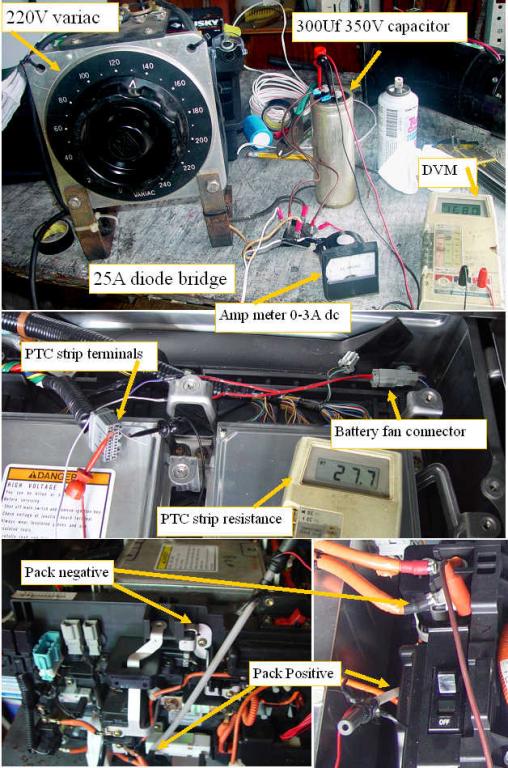
I gathered up the required components.
220V variac
25A 400V diode bridge
300Uf 350V cap
3A dc ampmeter
custom HV connection probe
several DVM's
We wired up the power supply and confirmed that I could get 0- 250vdc output range.
We flipped the pack switch and found that the pack was at 154V.
With the pack HV switch off, I attached my custom HV probe to the precharge resistor lead (+) and an alligator clip to the negative terminal. We raised the variac voltage until it was at the same 154V so we would not get a surge when the charger was applied to the pack by flipping the main switch.
I made up a fan connector so I could run the battery fan if required from an adjustable DC lab supply.
We also connected an ohmmeter to the PTC strip ends so we could watch the strip resistance change as the pack warmed up.
I started with a 2A charge, so we could get to the 100% SOC point as quickly as possible. We watched the battery voltage raise, and tweaked the variac voltage to maintain the 2A charge.The PTC strip started our test at 22.9ohms, which represented about 85F.
After 5 minutes or so, the PTC strip resistance started a gradual raise, and the pack voltage continued to raise.When the PTC strip got up to the 30 ohm range, I pulled the battery fan and used my non contact IR thermometer to see that the cells were at ~110F.I put the fan back in,turned it on and taped around the edges so it would draw air better. I used a digital thermometer to measure the outlet air temp, and found it at ~ 100F. The fan at 12V was really pulling a lot of air through the pack, so the PTC strip resistance rapidly began dropping towards the starting resistance, and the fan outlet air quickly dropped to ~88F.
Conclusion, with the fan running at 12V, there will be almost no measurable temperature rise even when charging at 2 A.
As the pack approached the 167V voltage we dropped the charge current back to 500MA, and left it there. The voltage of course dropped back a bit to 165V when the current was dropped, but after another 1/2 hour at 500MA, it pretty much stopped changing and settled at 168.9v.
We determined that the best way to determine when you are at the 100% SOC point is when the pack voltage stops raising. A simple rate of charge vs rate of change of terminal voltage determination should be all that is required if an automatic charger/balancer were to be built. When the high rate charge pack voltage rate of change slows down, we switch to the trickle rate, and again wait for the rate of change to actually stop changing, then we soak for say 1/2 hour and then stop the charging.
Ron drove back to NY, and found that the pack behaved much differently, and the charging would work much more normally. Unfortunately he will be not be able to drive the car for the next 3 weeks due to a medical issue.
We will have to wait 3 weeks to get the full report.
Ron has since started a hybrid battery pack rebuilding service.
|
|