|
Joystick Configuration & Calibration | 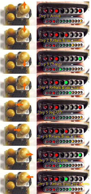 | | | Joy calibrate steps |
Joystick calibration: The flexibility of the joystick mounting and orientation options, and the ability to use two joysticks, make the joystick part of the system difficult to set up with a generic calibration. The biggest feature of this version of the code is this joystick calibration mode.
The joystick is such an central part of MIMA, that MIMA cannot be operated until this calibration is set, as it would not know which axis is the master assist/regen axis, or the direction for assist, regen, or jog up and jog down. If the system has not been calibrated(the first time you use it after installing this chip) it will switch right to the JOY calibration mode. If you change joysticks, want to add a second one, or want to change the direction for assist/regen, or jog-up, jog-down, you can reenter this mode by first stopping the car.
All joysticks should be connected at this time.
Press and hold the mode 2 button. First it will be in mode 2 (PIMA), hold it a bit more, and mode 2 with flashing mode 3, or the standard calibration mode is activated, with all the amp LEDs on for the display brightness calibration. Continue holding the mode 2 switch until the mode 2 LED goes off, and the mode 3 LED alone lights up. The maximum assist LED will also come on. Now you are ready to calibrate.
In the image, I am showing only one of the ways to configure the joysticks, either the X or Y axis can be assist, and the direction for assist and jog-up can also be different that the photo. We will use this illustration as the standard setup.
Step 1. The max assist LED is your cue to move one of the joysticks in the direction that you want to be assist. The joystick should be moved to the end of travel in that direction and held without moving in that position until the display flashes all LEDs, and turns on the minimum assist LED.
Step 2.The return from assist point will now be determined as you allow the joystick to return to center. It is important that you don't let it just snap back, or you don't push it. Just let the stick return with the built in spring. Let go of the stick, and once the system has read the same value several times in a row, the display will again flash all LEDs to confirm that this point has been determined. The display will then light the max regen LED.
Step 3. The max regen step is your cue to move the same joystick to the opposite direction from assist, and to hold it there until the display again flashes all LEDs to show that the point has been determined. Once that has happened, the min regen LED will light.
Step 4. The return from regen point will be determined when you let the stick return to the center, again being careful not to let it snap back or go beyond the natural spring return point. Once this point has been determined, the mode 3 LED will flash, and the max assist LED will again come on to indicate that you are ready to set the jog-up direction.
Step 5. The jog -up point will now be set. Move the joystick along the other axis in the direction that you want to use for jogging setpoints up. Once this has been determined, the min assist LED will come on.
Step 6. The return from jog-up will be set next as indicated by the min assist LED.
Step 7. The jog-down direction is next.
Step 8. The final position is the return from jog-down. At this point you are half way through the calibration. The display will revert back to the original not flashing mode 3 LED, and the max assist, ready to go through the whole sequence again with the second stick if you have it connected, or repeat with the same stick if you only have one.
The settings are the basis of calibration values that are stored when the procedure has been successfully completed.
The first move for each axis (max assist and jog-up) will let the system know which axis will be assist and jog, and also let it know what stick motion should be next. If you try to move in the wrong direction or wrong axis, any time after the first move on each axis, the display will show 10100101. When you return to center, it will again show the cue for the direction it is looking for.
Once the calibration is complete, the system will reboot and show the night rider pattern, and will operate with the new joystick calibration.
|
MIMA Operation : |
|
