New consulting relationship with GreenTecAuto begins
What actually goes wrong with the batteries????
A look at todays Hybrid and EV battery packs
Battery packs exposed
Keeping Warm In New England
Plugging into the SUN
Making a small solar concentrator
Building MIMA and the plug in adapters
Converting a telephone truck to electric
DIY dual pulse Capacitor Discharge Spotwelder
Chevy Bolt EV joins the family
Getting in shape while making electricity
Retirement
Replacing gasoline with solar electric lawn equipment
What is Genesis One?
How to stop the aging process DIY
MIMA Install Day 2005 a Big Success!
Building a hybrid car grid charger
Assembling the bases
building it bigger 4.5A
Calibrating the temperature
Calibration and test of components and boards
Charger # 1 goes into beta testing
Discharger # 1 / gridcharger cycler accessory
Fan and temp boards
Getting serious
Harnesses for the Insights are nearly finished
Helpers make it go much faster
Inside the overnight charger
Modified overnight boxes
More thermal testing
Moving towards the goal line
PTC strip monitor and charger shutdown circuit
Temp volts and current calibration fixture
Test of accuracy
The code
Thermal testing.
The weather slows us down
Tapping into the Wind
Expanding MIMA with the Distribution board ( users projects )

PTC strip monitor and charger shutdown circuit

PTC strip monitor and charger shutdown circuit
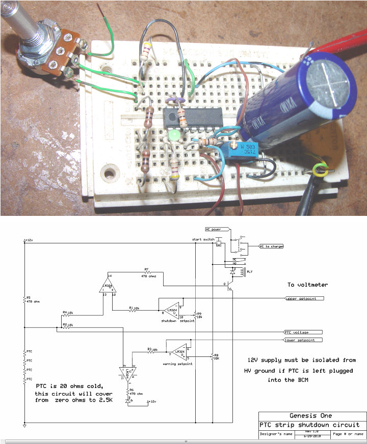
PTC monitor and shutdown

The mega charger can put out over 750 watts of power. If a really bad cell with high internal resistance is in the pack, it will get very hot very fast. Honda wa aware of that, and they built in the PTC strip with a resistive PTC sensor on each cell. These detectors will change resistance with temperature, and rapidly change from .16 ohms each to over 1200 ohms when hot.
Since we are not so much concerned with actual resistance as we are in resistance change, a simple resistance bridge circuit can easily monitor the resistance and allow us to set two thresholds of alarm. The first alarm will be set to turn on an LED to let us know that things are getting warm, and the second will unlatch the power relay that supplies the charger with AC power.
The only issue is that the dual charger ties the 12V fan supply negative to the HV negative to allow measuring the pack voltage. I suspect that the BCM would not like the pack negative to be connected to the PTC circuit, so an isolated 12V supply should be used for this circuit, or the PTC connector should be removed from the BCM.
PDF of PTC circuit