Discharger # 1 / gridcharger cycler accessory
|
 | |
|
Discharger/ cycler and internal resistance tester
|
OK, the chargers are almost all in the field, and I am looking at some accessories, that will make it work even better.
The first task that I will do is to design a charger controlled accessory that can actively discharge the battery as a unit, right in the car, so the charger can do automatic safe discharges to better cycle the pack.
Relying on driving the car to discharge the pack,can be less than reliable, as it has to be integrated into normal driving patterns which for most hybrid drivers is very un-natural, as we need to discharge the pack to a low value, by very aggressive driving. This is not safe, and wasteful of gas, as well as not really ever fully discharging , or completing a conditioning cycle.
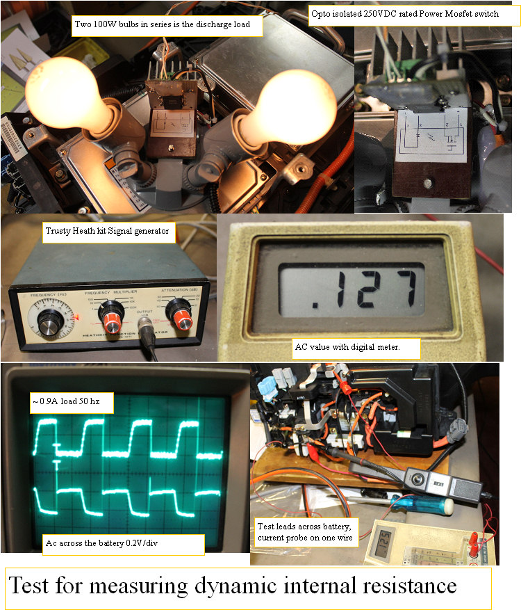
The Discharger#1 consist of a dual tungsten bulb holder, and a 250VDC rated power mosfet, that can be directly driven by the charger AUX port Under the side black cover. The high efficiency LED opto isolated gate control only needs 10-20MA to turn it fully on. and it can be turned on and off several hundred times a second if so desired.
I got to thinking about how nice it would be to be able to measure the packs internal resistance, so I set up a simple test. I connected my old heathkit function generator, and drove the mosfet with 50 HZ square wave, and measured across the battery to see the effect of the pulsing discharge current.
The signal measured with my storage scope, with AC coupling so I could see the AC component riding on the HV pack without seeing the DC volts.
The pack voltage varied in perfect sync with the pulsing, and I saw about .3V peak to peak, and with my current probe saw that the current pulsed up to about .9A.
The mosfet with the heatsink can switch up to 8A, so we can carry the concept further by using bigger bulbs. Of course a big power resistor would also work better,but they can cost $40-$70, whereas if your like me, you have replaced all the big bulbs in the house with LED bulbs, so you have a box of tungsten bulbs.
Since I know the current of .9A, and the voltage developed across the battery internal resistance of .125V, I can compute the internal resistance of the whole pack .127/.9 = .141 ohms.
A fixed resistor would be better than the bulbs, but this is good enough for comparison purposes, and is pretty cheap to make.
The charger voltage measuring system has .2V minimum resolution, so it cannot accurately measure this small AC voltage, but almost any digital voltmeter has a low AC volts scale.
So I am envisioning the dis charger doing a discharge of the pack, initiated by the charger via the AUX port,while the charger monitors the discharge voltage. A setable minimum voltage would be set up that would stop the discharge, and start a recharge.
As well as the adjustable absolute low voltage threshold, we will also determine the rate of discharge in volts per minute.
The voltage test will get a new value each 6 seconds, and when the rate of voltage drop increases beyond a fixed percent of the bulk rate of change, the discharge will stop due to a potential cell dropout or the whole pack reaching the end of its capacity. This assures that no cell will reverse, and that the cycle will end at a safe place. Kind of like a recalibration.
Repeated charge discharge cycles will erase the cells memory effect,and therefore extend the useable pack capacity in a precise and repeatable way.
At the end of the charge when the plateau is detected, we should see increasing capacity reflected by the measured charge AH value .
The Internal resistance measurement:
The charger would then be set up to pulse the dis-charger at 50HZ, and an AC voltmeter would read the AC component of the DC pack voltage that relates to voltage drop across the packs internal resistance.
The derived voltage was stable over 20-100HZ range with only a 0.003V change throughout the range, so I believe the number.
I will build the dis-charger into an extension harness like cable, so it can simply be inserted into the circuit between the charger and the charger connector on the harness, so the IMA box does not need to be opened.
Will do more testing on several packs, and see if the internal resistance numbers reflect real world internal resistance. Looks promising.
|
|
