The videos are finished, but they are not pretty. I am trying to upload some of them to You tube, and if successful, I will upload them all. I have been burning DVD's all day,(still doing it), and hope to have all that I need early tomorrow, so we will give each charger a final test, make sure that you get what you ordered, and ship what we have ready before the end of the day, and will continue to do that until all of the paid for chargers are shipped. The order of shipment will be based on many variables, but be assured that we will ship as many as possible every day until they are all in the mail.
The chargers will have a bag of install components like the screws, charger connector cover, drill templates,zip ties, mounting tape, upholstery removal tool, and some printed documents, and DVD instructional videos. Each charger will do a test charge on the big lead acid batteries, as well as being set up for the ordered cars and harnesses.
I will be putting upsome web based instructions if the videos don't make it to You Tube
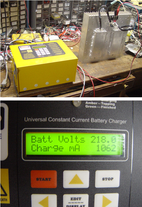
I will be providing three basic models, a Universal 1A overnight charger that can fill an empty hybrid pack (6.5AH)in less than 8 hours. A Universal maintenance charger that will be limited to 350ma. Universal indicates that the charger will charge up to 2a 230V pack The maintenance charger will also be offered specifically for the Insight, which would have a slightly smaller 12V power supply, and one less of the 48V supplies, and would have a maximum voltage output of 200V
All Universal units: 1. would be configurable for any voltage range all the way up to 250V as built, and with external voltage booster supplies to over 300VDC
2. would know when the voltage has reversed or stopped rising, at which point it would either A. turn it self off B. sound an audible and visual alarm, and continue trickle charging.
3. measure AH into the pack 4. have an LCD display and keyboard for viewing all of the measured values and allow entering calibration information. 5. run the fan, possibily with a variable speed based on temperature 6. Have a pack inlet and outlet air temperature probe. 7. The PTC strip resistance will be measured, which will also allow automatic shutdown in the case of a cell getting too hot 8. will have a timer that will shut off the charge after a preset time has transpired. 9. will have an auto shutdown mode where it will shut down after a setable amount of AH has been put into the pack. The shutdown functions will all be able to stop the charger, so the one that hits the setpoint first will shut the charger down. A battery maintenance mode which will have several submodes: Delayed Charge Charger is plugged into AC power and connected to battery. The delay time is set, and the charge start button is pressed. Charger will start after the time delay, and charge to full, then shut off. Time delay can be hours or months.
Auto maintain Charger is set to recharge to full when battery volts drops to a certain value, or after a specific amount of time.
All settings in all modes will come set up with recommended default settings for the car, with the ability for the user to change them in non volatile memory as we learn what works best.
Overnight charger: will charge at just over 1A until a programmable voltage setpoint at which point it will turn off the 700ma supply and continue at 350 ma, until it met the conditions for 2 above.
OK, the chargers are almost all in the field, and I am looking at some accessories, that will make it work even better. The first task that I will do is to design a charger controlled accessory that can actively discharge the battery as a unit, right in the car, so the charger can do automatic safe discharges to better cycle the pack. Relying on driving the car to discharge the pack,can be less than reliable, as it has to be integrated into normal driving patterns which for most hybrid drivers is very un-natural, as we need to discharge the pack to a low value, by very aggressive driving. This is not safe, and wasteful of gas, as well as not really ever fully discharging , or completing a conditioning cycle.
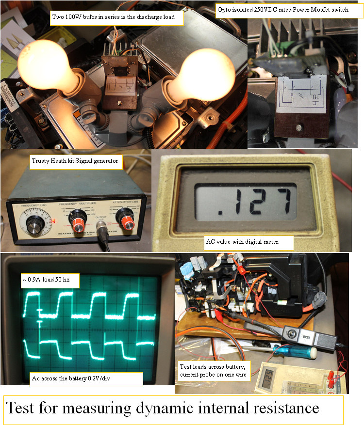
The Discharger#1 consist of a dual tungsten bulb holder, and a 250VDC rated power mosfet, that can be directly driven by the charger AUX port Under the side black cover. The high efficiency LED opto isolated gate control only needs 10-20MA to turn it fully on. and it can be turned on and off several hundred times a second if so desired. I got to thinking about how nice it would be to be able to measure the packs internal resistance, so I set up a simple test. I connected my old heathkit function generator, and drove the mosfet with 50 HZ square wave, and measured across the battery to see the effect of the pulsing discharge current. The signal measured with my storage scope, with AC coupling so I could see the AC component riding on the HV pack without seeing the DC volts. The pack voltage varied in perfect sync with the pulsing, and I saw about .3V peak to peak, and with my current probe saw that the current pulsed up to about .9A. The mosfet with the heatsink can switch up to 8A, so we can carry the concept further by using bigger bulbs. Of course a big power resistor would also work better,but they can cost $40-$70, whereas if your like me, you have replaced all the big bulbs in the house with LED bulbs, so you have a box of tungsten bulbs. Since I know the current of .9A, and the voltage developed across the battery internal resistance of .125V, I can compute the internal resistance of the whole pack .127/.9 = .141 ohms. A fixed resistor would be better than the bulbs, but this is good enough for comparison purposes, and is pretty cheap to make. The charger voltage measuring system has .2V minimum resolution, so it cannot accurately measure this small AC voltage, but almost any digital voltmeter has a low AC volts scale. So I am envisioning the dis charger doing a discharge of the pack, initiated by the charger via the AUX port,while the charger monitors the discharge voltage. A setable minimum voltage would be set up that would stop the discharge, and start a recharge. As well as the adjustable absolute low voltage threshold, we will also determine the rate of discharge in volts per minute. The voltage test will get a new value each 6 seconds, and when the rate of voltage drop increases beyond a fixed percent of the bulk rate of change, the discharge will stop due to a potential cell dropout or the whole pack reaching the end of its capacity. This assures that no cell will reverse, and that the cycle will end at a safe place. Kind of like a recalibration. Repeated charge discharge cycles will erase the cells memory effect,and therefore extend the useable pack capacity in a precise and repeatable way. At the end of the charge when the plateau is detected, we should see increasing capacity reflected by the measured charge AH value .
The Internal resistance measurement: The charger would then be set up to pulse the dis-charger at 50HZ, and an AC voltmeter would read the AC component of the DC pack voltage that relates to voltage drop across the packs internal resistance.
The derived voltage was stable over 20-100HZ range with only a 0.003V change throughout the range, so I believe the number. I will build the dis-charger into an extension harness like cable, so it can simply be inserted into the circuit between the charger and the charger connector on the harness, so the IMA box does not need to be opened. Will do more testing on several packs, and see if the internal resistance numbers reflect real world internal resistance. Looks promising.
(Posted 12/20/2011 by mikey)
Charger # 1 goes into beta testing
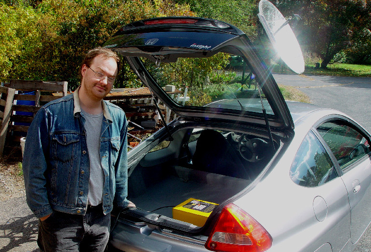
Charger #1 goes into beta testing. Iam Ian is the lucky owner.
Ian came up today, and helped with some charger test and calibration. His harness was the prototype for the Insight harness, so it made sense to let him also be the pre production code beta tester, so the first charger is now in the field, in the hands of a guy that can thoroughly go over the code operation, and help with the testing. So charger #1 has been delivered. Yea!
(Posted 10/15/2011 by mikey)
Calibrating the temperature
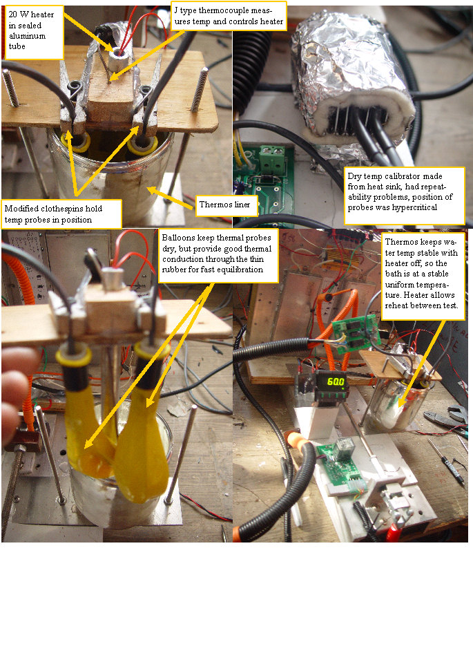
Clothespins ballons and thermos liner
Yes sometimes it takes several tries to get a fixture to do it's job as desired. The thermal calibrator was one of those. I start with a simple temperature controlled aluminum box, took to long for the air to heat the probes, as the leads were outside the box, and air could escape through the opening. Second fixture has aluminum heat sink with bent fins to make direct contact with the temperature probe chip, but due to the curved contact area, the position of the probes was very critical, and even with some thermal grease, was all over the place. After some thought, we made a water bath, with balloons to keep the probes dry, clothespins to hold the probes in position, and a heater to get the bath up to the required 120F that I want to do the calibration at. Warm up with the small heater takes a while, but once up to temp, I turn off the heater, and the thermos holds the temp very well, with only a 1 degree drop every 5 minutes. With the heater off, and some stirring, the bath is a very uniform temperature, so we can calibrate the inlet and outlet probes to be at the exact same reading. Since the probes are to measure the inlet to outlet temperature rise of the pack, it is important that they are matched.
(Posted 10/15/2011 by mikey)
The code
Writing the code
Some of you may have been wondering how I can be doing all the building and testing and still write the code. Fortunately I have an ace up my sleeve. Old friend, EE and experienced embedded controller designer and programmer Doug in Montreal has started with my early code, converted it from the mikroelectronica C dialect to the much more useful and easy to work with CCS C which will run in the MPLAB environment. We skype each other several times a day. Doug has an overnight charger, and is writing the code, I get the new code and test it as part of the charger testing, and give Doug my feedback so he can adjust the code. The program has grown from where I left it at ~30-40% of the chips programing space, and he is now at 91% full,as he puts the finishing touches on the code. We have accomplished virtually all of the stuff on the feature list, added some features and have a pretty easy to use fairley intuitive user interface. Nice job Doug.
(Posted 10/11/2011 by mikey)
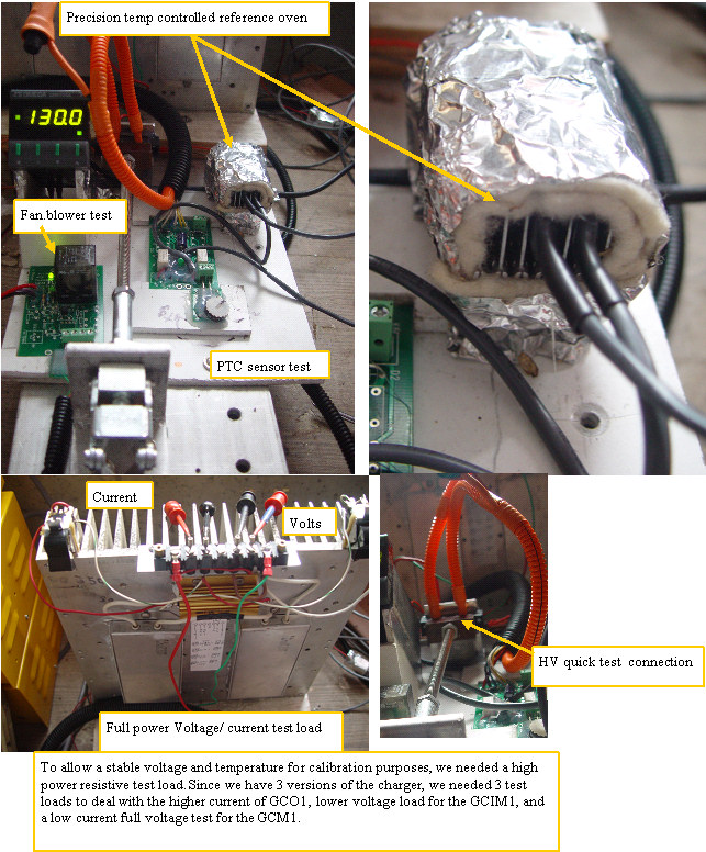
Temp volts and current calibration fixture
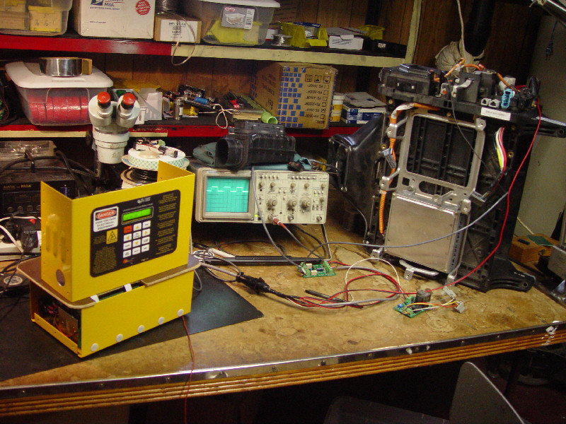
Calibrating and testing the chargers and harnesses
To make the test and calibration of the chargers and harness proceed as quickly and accurately as possible, I built a test fixture. The 100W resistors allow full power test, which presents a stable voltage and current, as well as a temperature controlled oven for an elevated stable temperature reference. This oven was made from a big aluminum heat sink. The fins are curved so they make spring pressure mechanical contact with the part of the temperature probe that is the sensing chip. This makes for reasonable warmup and settling times, which we use to test and calibrate the voltage and current analog signal conditioners, as well as being a 100% test of the charger harness and output connections.
(Posted 10/11/2011 by mikey)
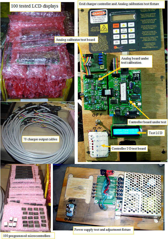
Calibration and test of components and boards
calibrating and testing
Very busy week of work, where I developed the fixtures for making the assembly and test process as efficient as possible. The analog card, controller card, power supplies, LCD displays, chassis assembly, all benefit from some simple fixtures to aid in the processes. Have captured the labor to assemble the chargers, now we need to determine the test, calibration, and final assembly and full power test labor. At that point we will have captured the whole process, and can get the pricing firmed up. Still have a lot of work to do to attach the fan and temp boards to the harnesses, fabricate more temperature probes, and then do a 100% wiring and functionality test of the complete harnesses, which will require another fixture. All of the controller and analog boards need to be run through the test and calibration process, and then the full charger will be assembled. Still have some quantity of controller and analog boards that have been stuffed, and need to be soldered, so any help we can get will make a huge difference at this point where all the pieces come together. Install instructions and video, operator manual, and finishing the software will be the final task, before we can be sending these chargers into the world. The devils in the details, and there are a lot of them in this project.
(Posted 9/18/2011 by mikey)
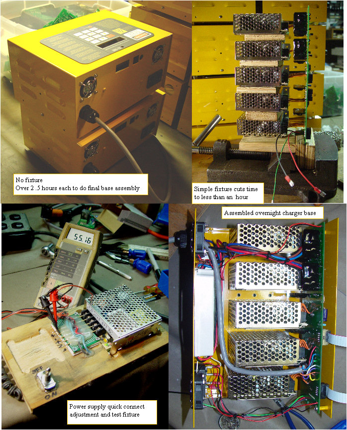
Assembling the bases
making the process go faster
In my attempts to capture the cost of assembling the chargers, I found that it took the better part of 3 hours just to connect the power supplies to the interconnect card, and get it all mounted in the chassis. I determined where the difficulties were, and made a fixture to support the boards and power supplies while assembling. The first charger I assembled with the fixture went together much quicker. With a few more under my belt to tune the procedure,and I will capture the cost. Then the maintenance. I had some help, for the last couple of days so I had to work with them to get as much done as possible. Should be able to finally tally up all the labor, so stay tuned for some final prices.
(Posted 9/16/2011 by mikey)
Moving towards the goal line
Almost have the parts for the existing orders finished
Update 9/11/2011 Have a lot more boards stuffed and finished. Have begun the connection of the temp and fan boards on the Insight harnesses, and have firmed up a workable first gen Civic harness and will make more copies for the orders in hand. Testing the chargers every day to get some experience using them. I ran into a problem with the wattage of a resistor on the interconnect board, so I need to replace the ones on the 60 boards that are built, and then I can start the final assembly of the chargers with a high degree of certainty that we will not have to take them apart again.
(Posted 9/11/2011 by mikey)
Harnesses for the Insights are nearly finished
Working with home generated power
Got the base harnesses as well as some controllers and fan boards built up despite the loss of power.
(Posted 9/3/2011 by mikey)
The weather slows us down
Zonked by the weather
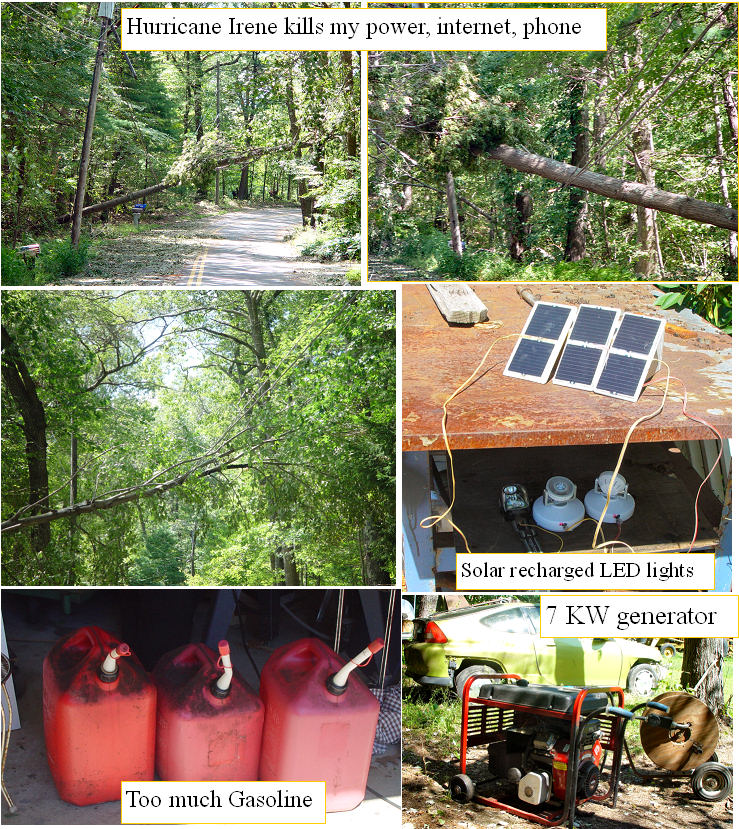
Nothing like a little hurricane to slow us down. Lost power, phone, internet for almost a week. Generator ate over $250 in gas,and I used my solar recharged electric telephone truck as a power source to run my freezer and fridge overnight, and was able to run them for over 12 hours on a charge that I was able to recover each day from my solar panels. Need bigger inverter, solar array,and battery bank. Built a few more solar chargers for my LED lights. We kept on working and made some good progress.
(Posted 9/3/2011 by mikey)
Helpers make it go much faster
Getting it built with help
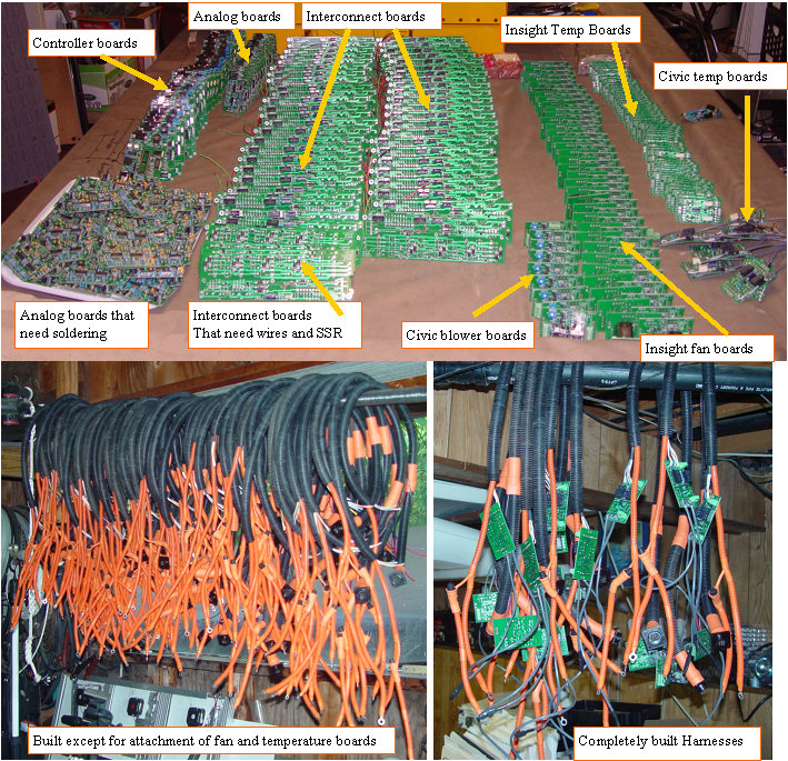
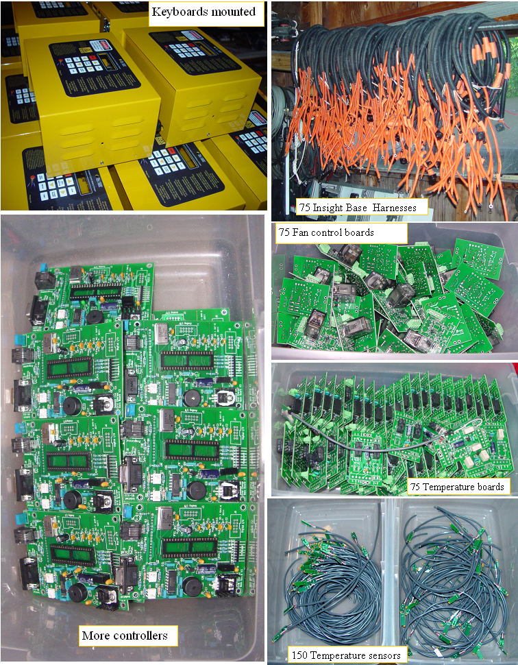
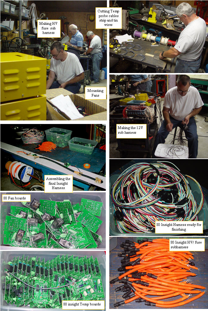
Had a nice day today as a civic owner while getting a grid charge, and an old friend joined Dan and I in our huge task. We have the fan and temp boards for 80 Insight harnesses made, and most of the 80 harnesses assembled. The fuse and short HV wire to the + tie point will have some HV orange wire loom as shown to add additional insulation and abrasion protection. We have finished mounting all the fans in the boxes, and have confirmed that all of the 5 new PC boards are working properly. After the harnesses are finished, we will finish up building of the many analog, Main controller, and Interconnect cards. The 200 + wires for the temp probes have been cut, stripped, and tinned ready for attachment to the already populated and tested temperature probes.
(Posted 8/24/2011 by mikey)
Fan and temp boards
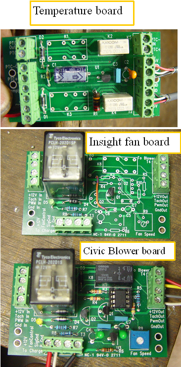
Temp and fan control boards
The blower and fan control board is the same for the Civic and the Insight, we just do not need to populate the PWM stuff when we use it on the Insight. The Temp board will sit just to the front of the BCM, and will have the PTC wiring pass through it so the PTC signal can be passed to the charger in a fully isolated way when the charger is connected.
(Posted 8/2/2011 by mikey)
More thermal testing
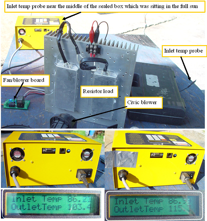
one hot little box
Figured I should do some thermal testing outdoors, as it was nearly 90F this afternoon. We punched two full sized fan holes on the prototype overnight charger. To start where the first test left off, we sealed the new fan holes so I could try the first variation. Variation #1 75F ambient Fan exhausting instead of blowing air into the box. Into the box test got up to 102F, out of the box only got up to 96F, which makes sense as the replacement cooler air is being drawn in through all the louvers, so it is distributed more evenly than when the box is pressurized, and we try to blow the air out. Variation # 2 75F ambient I connected a second fan, which was also drawing air out of the box, and the box then stabilized at 93F. Variation #3 Brought the test into an 85-90F outdoor environment. Temp got up to about 106F with both fans. Variation #4 Again sealed the second fan, and saw the box temp get up to 115F, and still rising, so I removed the tape, and after an hour we were back at a stable 107F Variation # 5 Did not get a chance to try a final variation where one fan blew in, and one out, but expect that it will not work as well as the both drawing air out, as it would virtually eliminate any fresh air frpm being drawn in through the louvers. Bottom line, I thing we should have two fans, and will run the 50 overnight charger boxes through the punch.
(Posted 7/31/2011 by mikey)
Test of accuracy
Full power battery charge
Before I send the PC boards to the board house, I wanted to determine how accurately the charger can measure the Current, Voltage, and Temperature. 250V with a 10 bit converter has ~0.2V resolution, and the current has about a 2 ma resolution. The temperature is about 0.3 degrees F resolution. Also wanted to see how clean the signals were. After making a few component changes I am satisfied that we have a reasonably accurate system. Of course I could have put in a dual slope or delta sigma stand alone A/D converter with higher resolution, but that would have added more cost and complexity. This seems to be good enough to do the job. Will finish up the PC boards with a much higher degree of confidence, and should be sending them out tomorrow afternoon. I did a thermal test of the Maintenance charger, and saw about a 35 degree F temperature rise, so I will be installing fans in those as well as the Overnight. The fan I will use is the Sunon MB40101V2-0000-A99. It has maglev bearings, and is rated at 7CFM. I ran the two chargers at full power connected to a kilawatt meter, and see that at 120VAC the Maintenance uses about 80 Watts, and the overnight was at ~ 240 Watts.
(Posted 7/26/2011 by mikey)
Modified overnight boxes
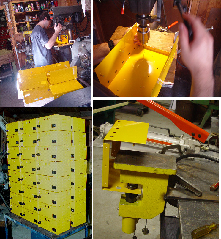
Fixing the boxes
Had some help today so we did all of the powder coating fixes, and also used the new 1.5" hydraulic punch to make the fan holes in all of the Overnight boxes. Unfortunately with all of the work on the boxes, I did not get the final production PC board designs out for quote, but should have them ready this week.
(Posted 7/22/2011 by mikey)
Thermal testing.
charger testing at full output
Set up a big load for testing the chargers. Test one with no fan showed a nasty 140F inside the charger case, so I mounted a 40mm CPU fan rated for 4.9CF/Min on the box and have run a second test. After 3 hours at full output, we are at a much more reasonable 102F in the box. The big heat sink on the other hand is at 130F, even with a 4" fan blowing on it. 500+ Watts in the closed battery box would definitely cook some cells, or worse yet if one cell had high internal resistance, it would dissipate much of the wattage, and get very hot. PTC and inlet to outlet temperature monitoring will keep things safe even in worse case conditions.
(Posted 7/19/2011 by mikey)
Inside the overnight charger
Inside the Overnight charger
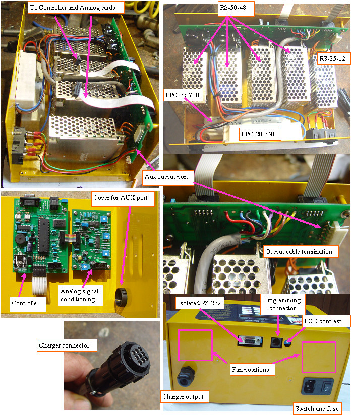
First full prototype is running. Found that we need a fan to dissipate the heat output of all the densly packed supplies. Should have anticipated this, as here is a lot of power in that box. 4- 50 W 48V supplies 1-35 W 12V supplu 1 35W 700 MA CC supply 1 20 W 350MA CC supply Photo shows the layout.
(Posted 7/19/2011 by mikey)
PTC strip monitor and charger shutdown circuit
PTC monitor and shutdown
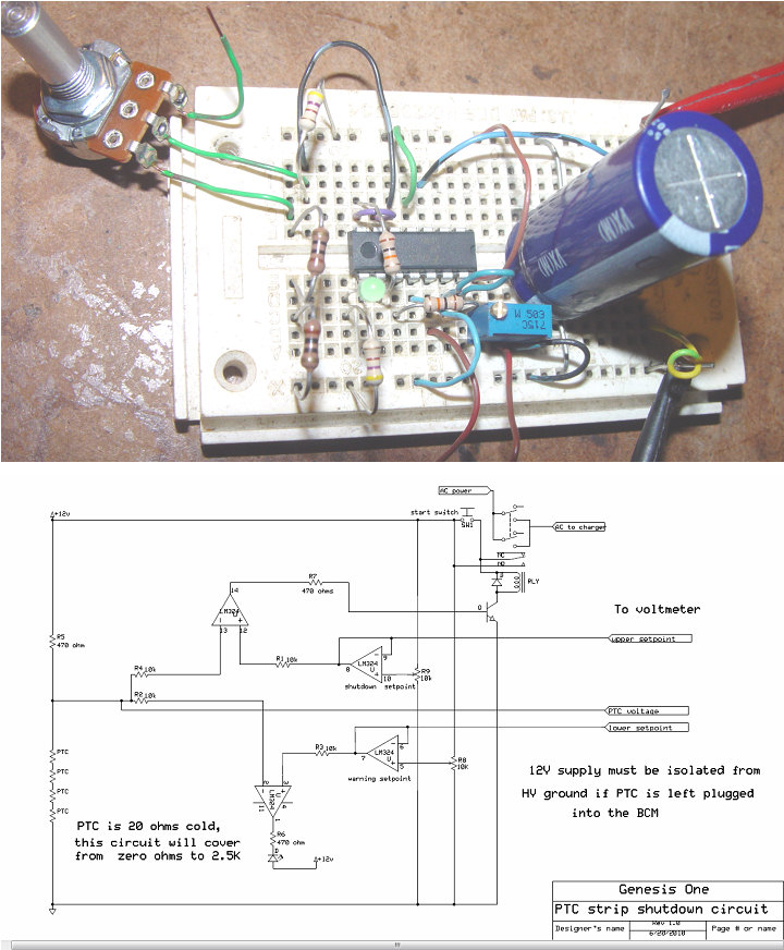
The mega charger can put out over 750 watts of power. If a really bad cell with high internal resistance is in the pack, it will get very hot very fast. Honda wa aware of that, and they built in the PTC strip with a resistive PTC sensor on each cell. These detectors will change resistance with temperature, and rapidly change from .16 ohms each to over 1200 ohms when hot. Since we are not so much concerned with actual resistance as we are in resistance change, a simple resistance bridge circuit can easily monitor the resistance and allow us to set two thresholds of alarm. The first alarm will be set to turn on an LED to let us know that things are getting warm, and the second will unlatch the power relay that supplies the charger with AC power. The only issue is that the dual charger ties the 12V fan supply negative to the HV negative to allow measuring the pack voltage. I suspect that the BCM would not like the pack negative to be connected to the PTC circuit, so an isolated 12V supply should be used for this circuit, or the PTC connector should be removed from the BCM. PDF of PTC circuit
(Posted 6/21/2010 by mikey)
building it bigger 4.5A
Mega charger
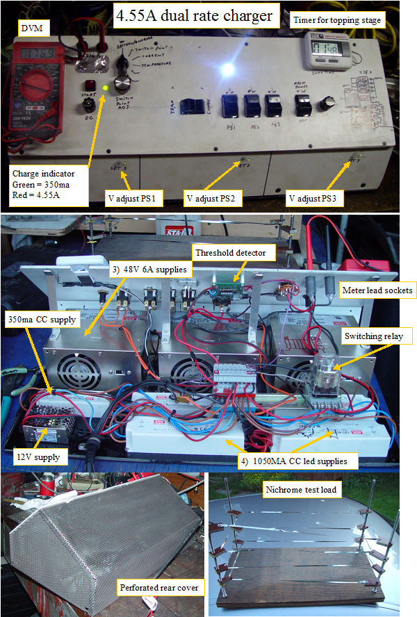
Hybrid Battery repair needs a way to top off the packs when he first gets them, and after they are finished. This dual rate charger pushes the max charge rate up to 4.55A,to safely top off the pack in minimum time by putting four 1050MA CC led supply in parallel with a single 350MA CC supply, in series with three 6A 48V supplies. The operation is the same as the overnight charger. Set the switchover voltage, push the red start button, and walk away. This is a one off unit, so it does not look like the chargers I will be making. The timer will start when the switchover happens. The test load should let me test the charger at full current. Will do first full power test tomorrow, then I will charge a real pack.
(Posted 6/18/2010 by mikey)
Getting serious
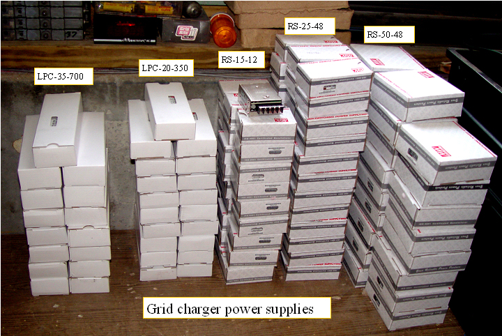
Future grid chargers
Nothing like buying a pile of parts to get one off their butt, and kick start a project. This neat little pile of power supplies is over $1500 worth of incentive.