Removing the ECMThe ECM is in a bad place to work, right under the passenger's feet. To remove the ECM so we can get at the connection points, is no small task, but with care, and patience, should go smoothly.
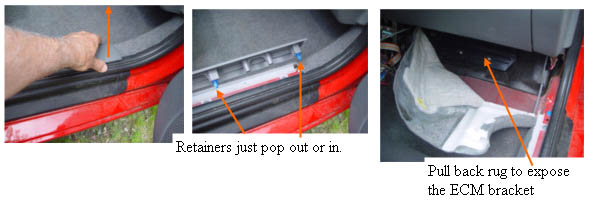
We start by removing the plastic cover over the door jamb, by pulling straight up, so the plastic clips pop out of the holes in the jamb.
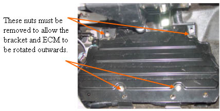
After the two nuts at the top, and the two bolts at the bottom of the ECM bracket are removed, lift the bottom of the bracket up and out, and rotate the assembly counter clockwise, to get at the final two screws that hold the ECM to the bracket.
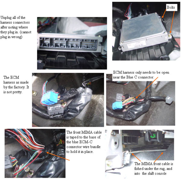
The bracket and ECM are rotated outwards. Be very careful not to pull out any wires, this should rotate with little strain on the harness if you do it correctly. Remove the last two bolts that are holding the ECM to the bracket, then remove the bracket.
Unplug all of the harness connectors after noting where they plug in. (cannot plug in wrong)
|
First we will connect the wires to the ECM side of the cable. Carefully strip an area of the insulation of the target harness wire by prying the insulation back without cutting any strands of wire. Then using the same twist solder and tape techniques as all the other wires, make the six connections. This is the most difficult step of the whole installation, as the harness is in a bad place to work comfortably. I found it easiest to kneel on a soft cloth just outside the open passenger door while leaning into the car to make the connections.
|
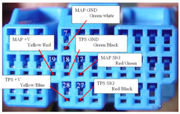
ECM C-28 Yellow/blue wire to MIMA ECM ribbon Orange wire
This connection brings the +5V from the TPS circuit into the MIMA front cable. TST the connection.
|
ECM C-27 Red/Black wire to MIMA ECM ribbon Gray wire TPS
This connection brings the TPS 0-5V signal into the MIMA front cable. TST the connection.
|
ECM C-18 Green/Black wire to MIMA ECM ribbon Violet wire TPS
This connection brings the TPS ground wire into the MIMA front cable. TST the connection
|
ECM C-19 Yellow/Red wire to MIMA ECM ribbon Blue wire MAP +V
This connection brings the MAP +5V into the MIMA front harness. TST the connection.
|
ECM C-17 Red/Green wire to MIMA ECM ribbon Black wire MAP
This connection brings the MAP signal into the MIMA front harness. TST the connection.
|
ECM C-7 Green/White wire to MIMA ECM ribbon White wire MAP gnd.
This connection brings the MAP gnd. into the MIMA front harness. TST the connection.
|
Level 2 install: |