Welder first test
|
 | |
|
Getting closer
|
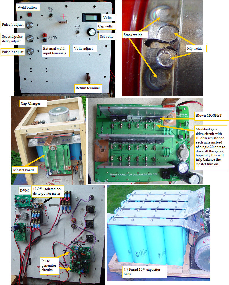
I finally got back to the big spotwelder. I made a case and front panel for the welder.I put the thing on some small casters so I could easily move it around. The aluminum buss bars were attached to the positive copper weld terminal, and the mosfet board was mounted to the negative aluminum buss bar. The connections were cleaned with steel wool, and coated with dielectric grease before joining.For the pulse generator circuit I used two dual edge triggered cmos one shots (74c221). The "WELD" input fires a 10us oneshot. This oneshot makes a nice short trigger signal for cleanly firing the oneshot for pulse 1.This pulse is adjustable between .1 and 8 ms
When this pulse finishes, it fires a delay one shot that is adjustable between .05 to 30 ms
When the delay one shot finishes, it fires the pulse 2 one shot, which is adjustable between .1 and 32ms
The pulse 1 and pulse 2 pulses are diode or'ed to fire the mosfet board.
It seems to work pretty well. I will make calibrated pulse and delay dials for the control pots, and it should have all the control I will need.
I gradually increased the two pulse widths and tried various test loads to get a feel for the system. Next I set up the cell welder and tried some welds on a real subpack between the stock welds. Even at the short pulse side of the adjustment range, the welds looked fully formed and solid. Like any curious person, I continued to turn up the pulse width to see what would happen. Bang! after a weld at about the half way point on my adjustments, the mosfet board did not turn off. The board had about 170 ohms when measured with an ohmmeter.
OK how do I find which of the 18 parallel mosfets is the problem, without destroying them or the PC board.
I found that with the power on, I had 13V of gate drive, when it should have been zero.
One of the likely failure modes is gate to source or gate to drain, but since all of the gates were tied together, there was no way to isolate which was shorted, and the gate drive was keeping all the good mosfets on so the whole mess of mosfets was always on.
I cut the gate drive etches, and soldered a 10 ohm resistor into each gate circuit, so they were somewhat isolated. Sure enough, as soon as I turned the system back on, one mosfet gate was at 13V while the rest could be held at ground.I changed the mosfet and the problem was solved.
Since each mosfet has a different turn on threshold,which can be over 2V different from other mosfets, this will always cause the mosfet with the lowest turn on threasold to turn on first. By having the gates isolated with the resistor, each gate is independent and will turn on based on the RC time constant of its gate capacitance and the 10 ohm resistor.This configuration should better balance the turn on and turn off time, so all 18 mosfets are sharing the load.To Be fair, the mosfet board was designed for ~ 3 Farads, so My 4.7 farad Cap bank requires a better snubber network because of the higher energy.
Next I need to get the built in charger operational, and continue testing, but this looks much better than the big SCR already.
|
|
