New consulting relationship with GreenTecAuto begins
What actually goes wrong with the batteries????
A look at todays Hybrid and EV battery packs
Battery packs exposed
Keeping Warm In New England
Plugging into the SUN
Making a small solar concentrator
Building MIMA and the plug in adapters
Converting a telephone truck to electric
DIY dual pulse Capacitor Discharge Spotwelder
Cell Miller mounting the components
Welding beautifully
More snubbing
Beefing up the switching board
Rebuilding the welder
Need better welds
Welder first test
Making some cells for weld testing
More parts of the process
New weld head
Spotwelding fixture #1
More energy
First weld testing
Making a spot welder??
Chevy Bolt EV joins the family
Getting in shape while making electricity
Retirement
Replacing gasoline with solar electric lawn equipment
What is Genesis One?
How to stop the aging process DIY
MIMA Install Day 2005 a Big Success!
Building a hybrid car grid charger
Tapping into the Wind
Expanding MIMA with the Distribution board ( users projects )

More snubbing

More snubbing
SNUBBER

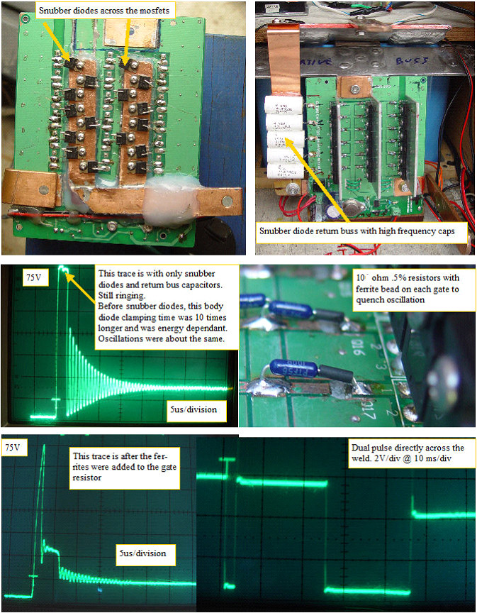
The initial mosfet board saw a huge inductive back emf HV spike that was clamped to ~75v by the mosfet body diodes,but the energy dissipated would get bigger as the weld duration went up, eventually causing mosfet failure. Adding the snubber buss and schottky diodes did a nice job of limiting that HV pulse energy, which made the back emf pulse width a constant. The oscillation issue was caused by HF feedback getting into the gate drive buss,due to the parallel pc board traces and this caused the mosfet board to ring after it was supposed to turn off.
I added ferrite beads in series with the 10 ohmto suppress the oscillations, and as the traces show, that seems to be working.
The last thing to do is to get the High current charger circuit working, so my pulse frequency can be increased.