A year and a half, and I am getting down to the last of the MIMA systems. The plug in boards have performed nicely, with only a few issues like an additional pin required for Japanese insights and the 2006 model year. My 100% testing only let one intermittent connection get by. Now I am running out of built joysticks and plug in adapters so I have to set up the production line again for the last time, but this time I need to build all of it my self. The plug in adapters while the best Harness to date, take several hours each to build,and the components are expensive as well. The controller and circuit boards hours more,and more parts, Joystick and display more cost and time in hand fabrication and assembly. This Is why the Plug in MIMA will not be built again, I could work for burger king and make a better hourly wage.
TPS smoothing mod
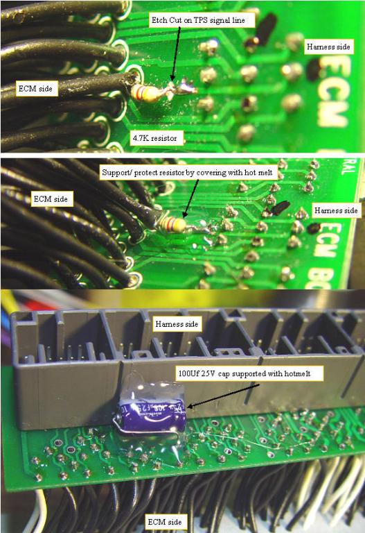
TPS smoothing mod on ECM plug in board
If the throttle signal is fed through a 4.7K resistor with a 100Uf cap to TPS ground, the effect is to smooth the TPS signal which is equivalent to holding your foot real steady. The new plug in boards allow making the modification on the plug in rather than to the car harness. An etch cut is made to the TPS signal line between the harness and the TPS input to the ECM. A 1/8W 4.7K resistor is attached to bridge the cut, and is covered with hotmelt to protect and support the resistor. The larger capacitor is mounted on the other side of the PC board and is also supported with hotmelt. The parts are cheap, but it is time consuming to do it well.
(Posted 11/2/2008 by mikey)
Building a better joystick
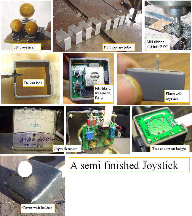
Finishing the MIMA joystick
All previous systems came with a bare PC board with joystick and two switches,some epoxy putty, and some on line examples of how one may finish the joystick with some careful putty application.I personally made an epoxy box around the board that allowed me to put leather over the epoxy, with the two switches just below the leather so they could be operated by pressing the leather above them. It makes them difficult to press by accident, and keeps the dust out. I felt bad that even at the higher price for the system, I only had a bare board joystick. Wanting to give you guys a finished system, I came up with a way to finish each joystick to a nice looking version of my joystick.The process doubled the labor and adds some cost to each joystick, but I will absorb that so your job will be much easier. Enjoy!
(Posted 11/1/2008 by mikey)
MIMA construction crew
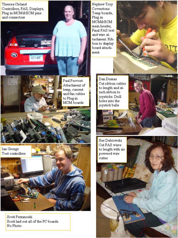
MIMA Helpers
I want to thank the people that made this run of MIMA possible. Cousin Scott who laid out the MIMA boards. Theresa Cleland who built most of the PC boards, and attached the thousands of wires with pins to the plug in boards. Nephew Troy who cut off the right angle wires of the plug in headers,attached them to the PC boards, Attached wires to the led displays, temp boards, FAS boards. Wife Sue who cut the hundreds of FAS wires. Paul Provost who finished the plug in MCM boards by attaching the two temp probes, current sensor and fan wires. Ian George who tested the controllers Dan Dumas who cut and attached the ribbon cables and connectors to the joystick boards, and drilled all the wooden joystick balls.
(Posted 10/25/2008 by mikey)
Making the plug in boards
Making the plug in boards
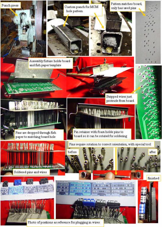
Getting the pins and wires in the correct position on the boards and connectors is of utmost importance. After a lot of careful analysis of the issues, I came up with a fixture that minimizes the possibility of miswiring, allows all pins to be double checked for position, holds the wires for soldering,and puts the required fishpaper insulation where required. Using the board as a template, I made a punch for my punch press that punches out clearance holes into the fish paper, wherever there is a required wire. The fixture holds this paper template over the board so the wires can be passed through the fishpaper hole, then the board. Any miswiring shows up as the wire will not be parallel. Once all the pins are in place, a rubber covered clamp holds all the pins to the board, so the fixture can be rotated for soldering. Once all the pins are soldered in place, a special tool is used to rotate the connectors into the correct orientation for insertion into the connector body. A photo of the pin locations is used as a guide for the insertion process. A 100% continuity check will be performed on the completed sub assembly as a final test.
(Posted 10/25/2008 by mikey)
Making a connector
Making the current sensor plug in adapter
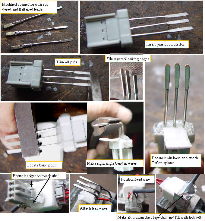
Like any multistep construction project,building the 3 pin right angle current sensor plug in adapter can be accomplished in many ways. The best procedure will be the one that gives the best results in the minimum amount of time. After several connectors, I got it down to a simple process. The wires were all cut to the correct length+ 1/8 inch. They were crimped onto a receptacle then soldered, as a crimp onto solid wire will tend to loosen over time if not soldered. The receptacles need to be sanded to reshape them to fit correctly into the stock male plugs. The plugs also need to be modified. The pin ends are cut off so they are all the same length, then a tapered lead in is filed onto the end of each pin.The wires with receptacles are plugged into the plug, and the rear of the connector has some hot melt applied to seal the rear of the cavity, and to secure the teflon strip that stops the hotmelt from getting into the locking tab. The cast shell is used to determine exactly where to bend the leads for the right angle, then it is tacked at the corners with more hotmelt. The three lead wires are soldered to the pins. Finally a dam made of aluminum duct tape is carefully formed, and is filled with hotmelt to protect and secure the lead wires.A lot of work, but it is a nice secure connection and should not give us any problems. To make sure we do not get any corrosion, the systems will include some protective connector jelly to protect the pins.
(Posted 10/14/2008 by mikey)
All of the parts are nearing completion
MIMA oct 11
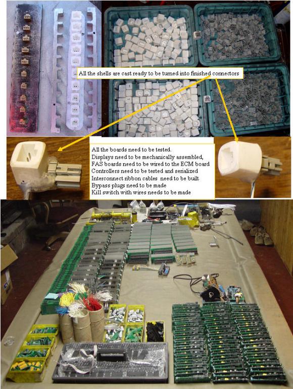
All of the components are ready for the final assembly and test. If anyone in the area would like to come over and lend a hand,it would help speed things up a lot. Jobs for everyone. Just give me a call when you can spare some time.
(Posted 10/11/2008 by mikey)
Making the current and fan connector shells
casting connector shells
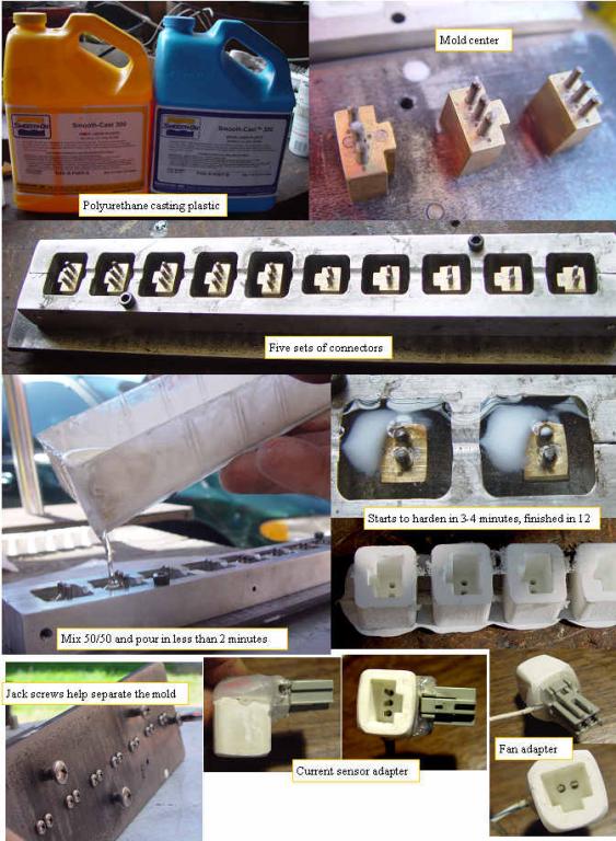
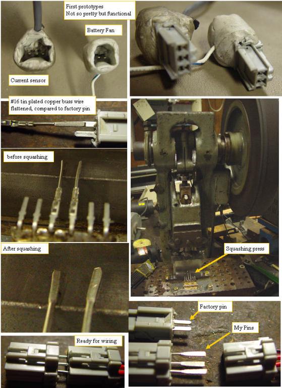
To make the fan and current sensor connectors be a true plug in, I needed a form fitting plastic cavity that had the flattened pins in the correct position for plugging in the stock harness. It must support the connector, align the pins with the harness connector, and will not allow the connector to be plugged in incorrectly. I made a mold, and after trying epoxy putty, and several other ideas, I found a two part urethane casting plastic, and found that it works great. the cast part is tough and stable. I finish all sides of the cast parts with a belt sander to clean them up. The first two prototypes look and feel solid.
(Posted 10/10/2008 by mikey)
Building the display components
making the display parts
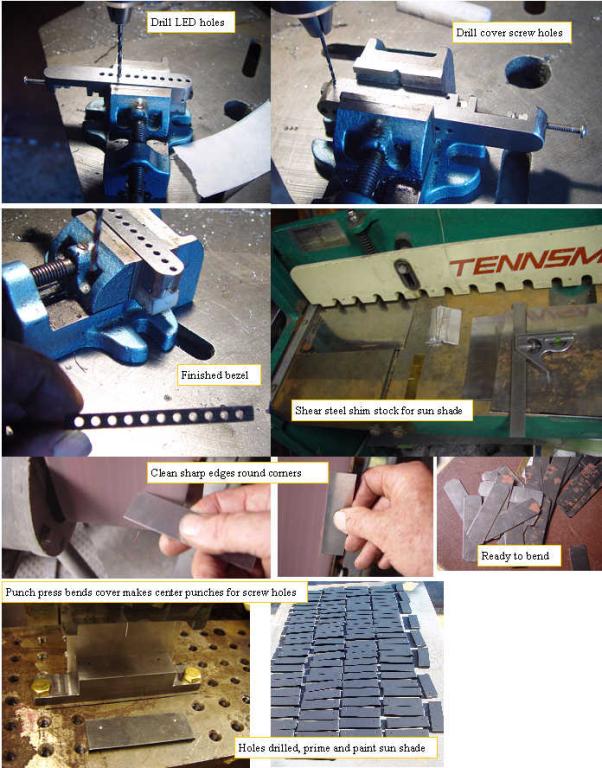
The new display still needs the black plastic bezel and metal sun shield. I made a fixture for drilling the led holes and the cover attachment tapped holes. I sheared the 1" strips, and deburred the edges. I made a punch fixture that bends the metal sun shade sides, and punches center holes for the mounting screws. next was degreasing, priming, and painting of the covers.
(Posted 10/2/2008 by mikey)
PLUG in adapters for fan and current sensor
Forming the male pins
After striking out on identifying a source for the socket side of the fan and current sensor connectors, I needed to figure out how to make 500 male female pins for the 3 pin and 2 pin connectors. I want the adapters to securely support the harness connector that will plug into the adapter, be low profile, and be strong and reliable connections so the stock signals are not effected. The honda connectors pins are almost exactly the same width and thickness as the larger of the Amp Tyco connectors, but it is not cost effective to pull the 13 pins out of the $12 104 pin headers, so I did some experimenting and found that #16 tin plated copper buss wire if squashed to the .024" thickness that the stock pins are, gets to nearly the same width as the stock pins, and the squashing seems to leave the tin plating intact. I used the display cover punch fixture with a pin holder made from a cabinet hinge, to hold the pins in the correct position for squashing. The resultant pin is strong, and easy to attach wires to, and I can get 350 of them out of 1/4 lb roll of the wire. Next task, the connector shell.
(Posted 10/2/2008 by mikey)
The Plug in adapter boards are here and are being built
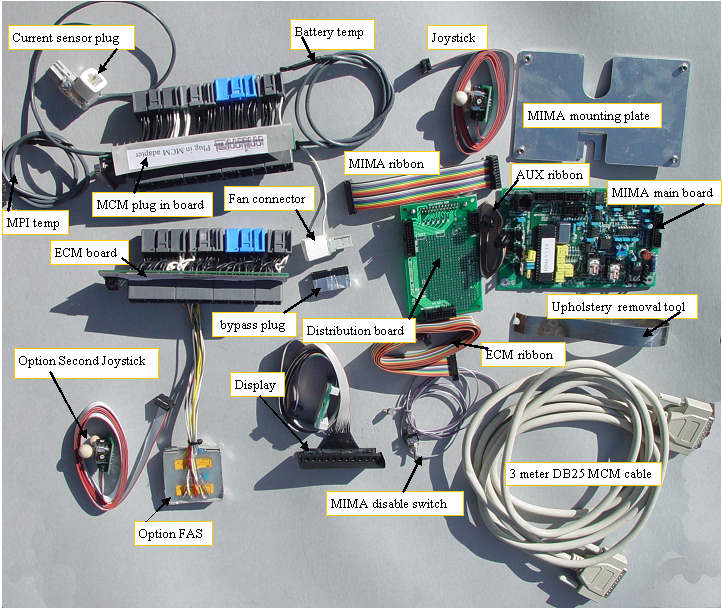
The final boards finally
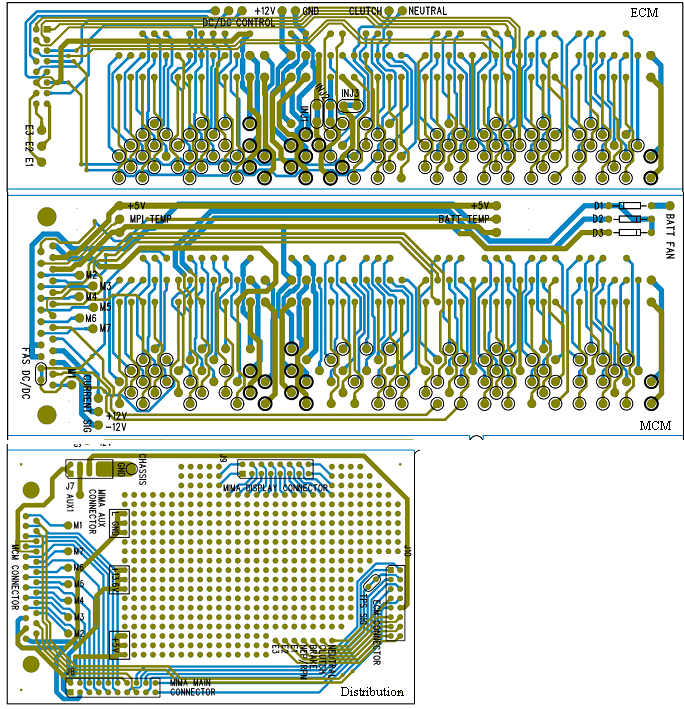
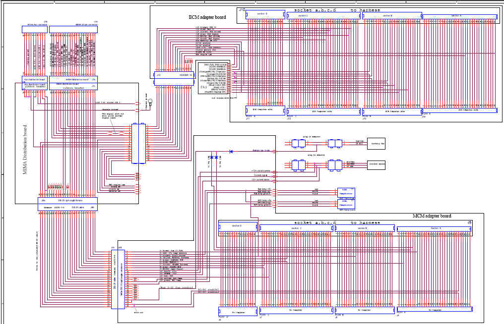
The final plug in boards are in hand. Blue is top side, green is bottom side. The ECM boards have pads to attach the FAS system.Three etch cuts at the fuel injector locations (oval silk screen)are required when FAS is attached. A single etch cut on the DC/DC enable line on the MCM board is required when FAS is used.The circles around a pad indicates that a pin wire must be attached. The thick circles indicate a large pin, thin is a small. The ECM board has three extra conductors, E1,E2,E3, which can be used to bring any ECM signal to the distribution board. The Neutral,Clutch, Brake, and NEP(rpm) signals are included on the ribbon. The MCM board has pads for seven spare conductors, M1 through M7, which can be used to bring MCM signals to the distribution board. The distribution board ties everything together. A breadboard area provides a place for expansion, both as a breadboard, or a place to mount a future interface board. The display 16 conductor ribbon connector can be plugged into the breadboard so other displays can be interfaced to that port. This expandable harness interface should provide all the future expansion that we will require to take the MIMA system to the next level, while making the system much simpler to install.