Making the plug in boards
|
 | |
|
Making the plug in boards
|
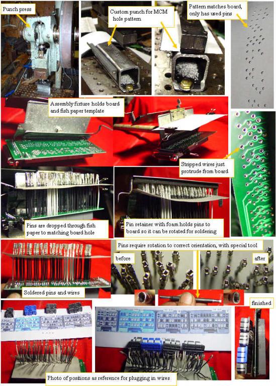
Getting the pins and wires in the correct position on the boards and connectors is of utmost importance. After a lot of careful analysis of the issues, I came up with a fixture that minimizes the possibility of miswiring, allows all pins to be double checked for position, holds the wires for soldering,and puts the required fishpaper insulation where required.
Using the board as a template, I made a punch for my punch press that punches out clearance holes into the fish paper, wherever there is a required wire. The fixture holds this paper template over the board so the wires can be passed through the fishpaper hole, then the board. Any miswiring shows up as the wire will not be parallel. Once all the pins are in place, a rubber covered clamp holds all the pins to the board, so the fixture can be rotated for soldering.
Once all the pins are soldered in place, a special tool is used to rotate the connectors into the correct orientation for insertion into the connector body.
A photo of the pin locations is used as a guide for the insertion process. A 100% continuity check will be performed on the completed sub assembly as a final test.
|
|
