I had a lot of experience with Unitek precision spotwelders when I worked at the level gauging company. We were welding a .003" gold flashed nichrome wire to a .04"X .75" 301 SS strip. The electrode pressure, weld pulse lengths and electrode cleanliness had to be just right or the wire would blow away. I also have two of the transformer type spotwelders that are used for autobody work. Based on this experience, I am well acquainted with subtleties of this powerful welding technique. The need to weld battery cells into subpacks to repair hybrid batterypacks gave me a reason to build a good sized spotwelder, and since the cells needed to be welded with minimum heat effected zone,the very rapid high current pulse from a capacitor discharge welder is the best solution. This blog describing the construction and development of the welder starts at the bottom of the page.
Cell Miller mounting the components
Stand alone weld removing fixture
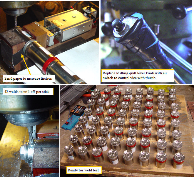
The cell clamping vise that I made earlier was clamped in my bridgeport milling machine vise when I used it to separate the cells. I want to make the fixture not depend on the milling machine, so I gathered up some parts I had, and made it into a small dedicated milling machine just for the purpose of removing welds.
(Posted 7/10/2010 by mikey)
Welding beautifully
New Weld fixture looking good
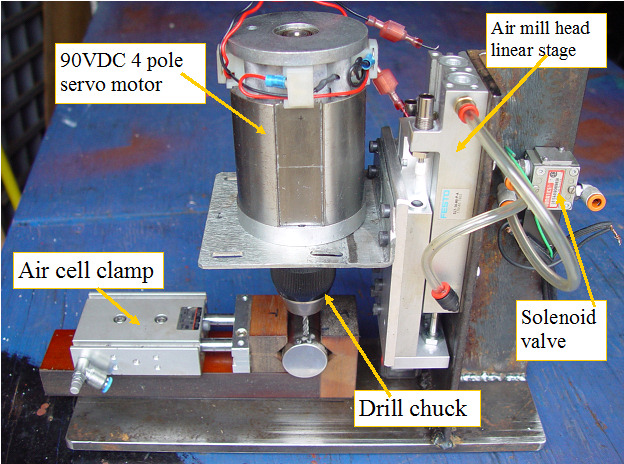
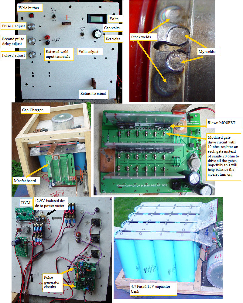
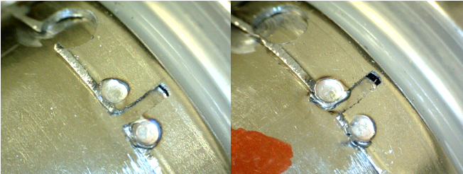
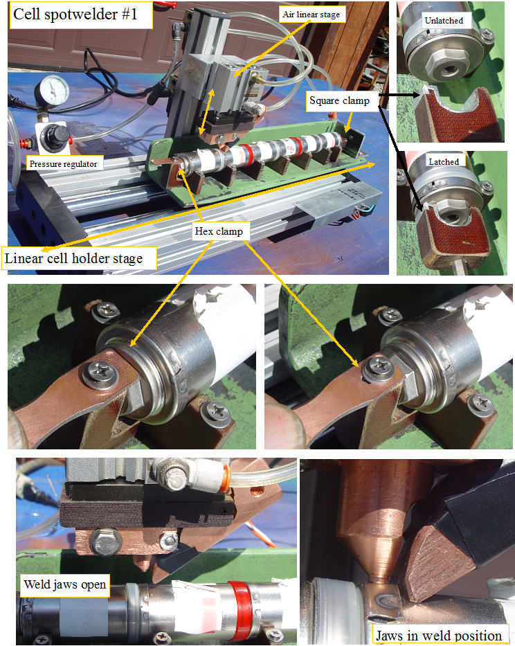
Finally got back to my spotwelder. For production welding I determined that my weld head had to have certain features. 1. easy to align 2. easy to build 3. automatically adjust to uneven surfaces 4. be able to press the contacts into the cells with up to 300 lbs of force 5. easy to replace the weld tips with minimal time required for changeover and adjustment.
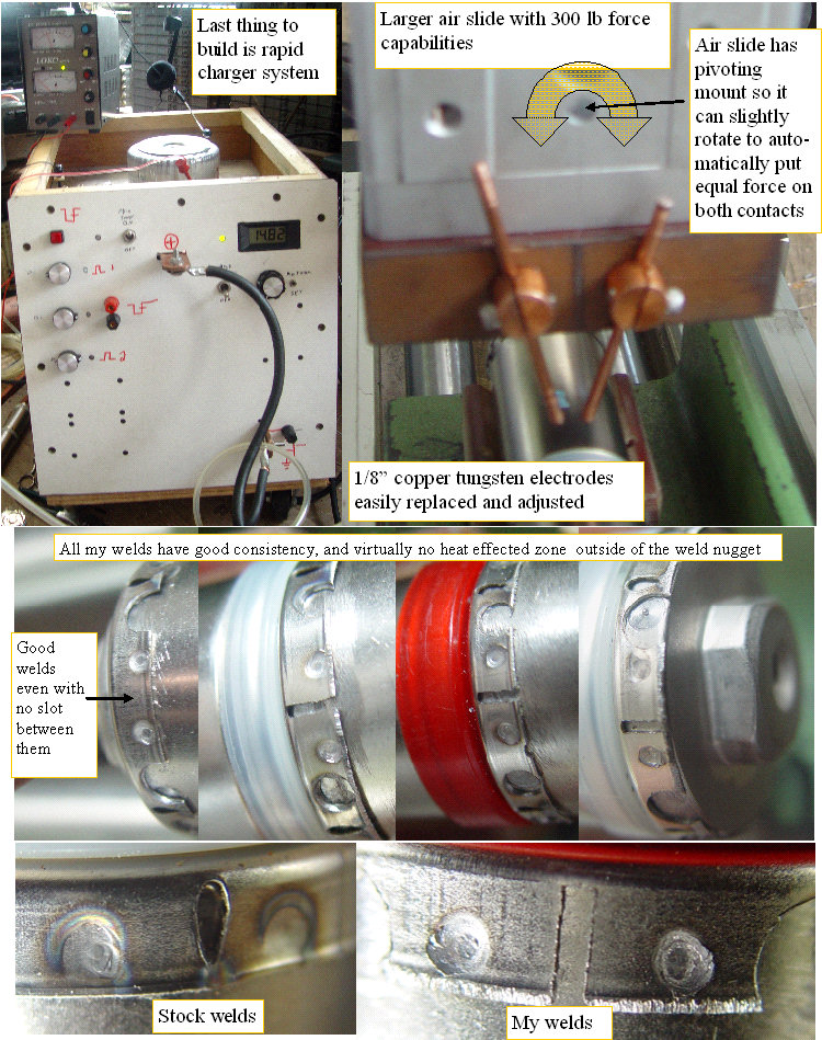
The new design uses a much bigger air powered slide that can provide over 300 lb of force @ 100psi inlet pressure. The slide is mounted to a bridge assembly so the mount will not deflect when pushing. The welding rods are clamped by a set screw, and can slide in or out easily. The rods pass through a hole in a 1/2" copper bar that is tapped on the rear side so the large ring terminals of the weld cables can simply be bolted on with some 1/4-20 bolts. The cell supports were changed to full V blocks to better support the cells under the high contact force. The 1/2 " rods pass through a block of linen phenolic and are held in position by two set screws. Very easy to make, and it allows a lot of adjustment flexibility. The welds look good, and I only had one blow out, when I turned the second weld pulse way up. I can dump >90% of the 15V 4.7 Farad capacitors charge into the weld if required, but it only takes bit over half to make good welds. I even can weld without the slot between the contacts. The best part is that it makes welds over a wide range of timing variations. The only thing I don't like about the design is that the first short conditioning pulse is using the max cap voltage, and the second one only has whats left for voltage to work with. Once I can charge the cap at 50A instead of 3A, that difference should be negligible and will be controlled by the delay for charging before the second pulse. In all, I think I have a dual pulse CD welder that is nearly ready for production use.
(Posted 7/8/2010 by mikey)
More snubbing
SNUBBER
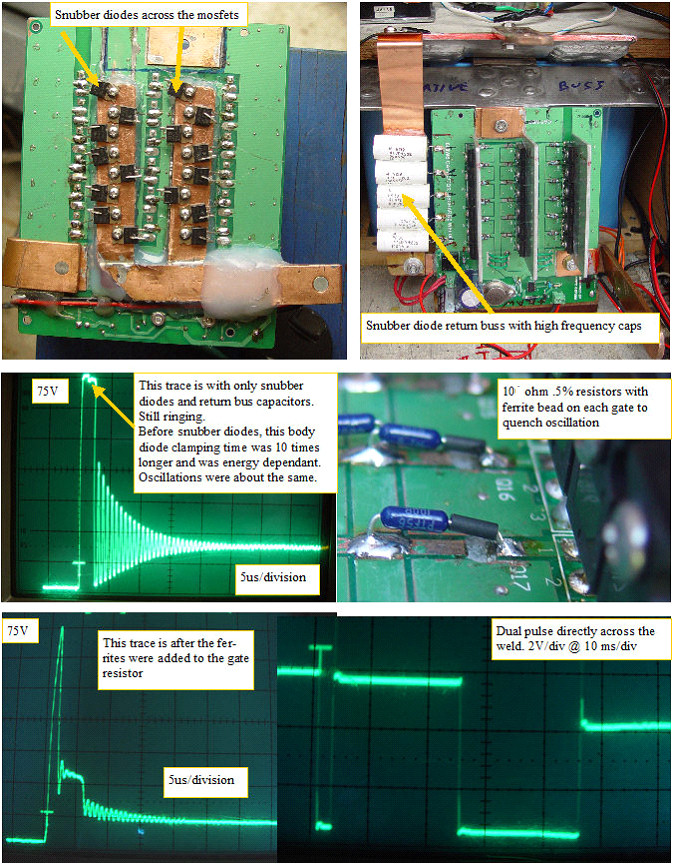
The initial mosfet board saw a huge inductive back emf HV spike that was clamped to ~75v by the mosfet body diodes,but the energy dissipated would get bigger as the weld duration went up, eventually causing mosfet failure. Adding the snubber buss and schottky diodes did a nice job of limiting that HV pulse energy, which made the back emf pulse width a constant. The oscillation issue was caused by HF feedback getting into the gate drive buss,due to the parallel pc board traces and this caused the mosfet board to ring after it was supposed to turn off. I added ferrite beads in series with the 10 ohmto suppress the oscillations, and as the traces show, that seems to be working. The last thing to do is to get the High current charger circuit working, so my pulse frequency can be increased.
(Posted 6/26/2010 by mikey)
Beefing up the switching board
Beefing up the switching board
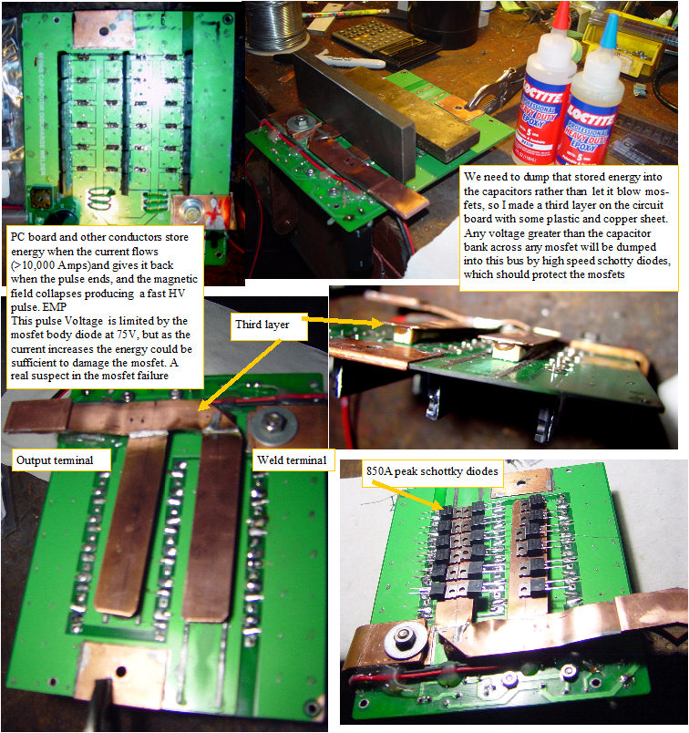
I got the replacement mosfet, and some precision 10 ohm resistors. I also got some high speed high power schotty diodes to dump the big HV spike into the capacitor bank instead of letting the voltage stress the mosfets. This is possibily an overkill, but I will be making millions of welds with this thing, and don't mind spending a few bucks getting things as solid as I can. This buss will connect with a copper buss bar to the capacitor positive buss. Any voltage greater than the capacitor bank voltage will conduct through the diode and buss bar right back to the capacitor. That's the plan, will soon see if the plan works.
(Posted 6/10/2010 by mikey)
Welder first test
Getting closer
I finally got back to the big spotwelder. I made a case and front panel for the welder.I put the thing on some small casters so I could easily move it around. The aluminum buss bars were attached to the positive copper weld terminal, and the mosfet board was mounted to the negative aluminum buss bar. The connections were cleaned with steel wool, and coated with dielectric grease before joining.For the pulse generator circuit I used two dual edge triggered cmos one shots (74c221). The "WELD" input fires a 10us oneshot. This oneshot makes a nice short trigger signal for cleanly firing the oneshot for pulse 1.This pulse is adjustable between .1 and 8 ms
When this pulse finishes, it fires a delay one shot that is adjustable between .05 to 30 ms When the delay one shot finishes, it fires the pulse 2 one shot, which is adjustable between .1 and 32ms The pulse 1 and pulse 2 pulses are diode or'ed to fire the mosfet board. It seems to work pretty well. I will make calibrated pulse and delay dials for the control pots, and it should have all the control I will need. I gradually increased the two pulse widths and tried various test loads to get a feel for the system. Next I set up the cell welder and tried some welds on a real subpack between the stock welds. Even at the short pulse side of the adjustment range, the welds looked fully formed and solid. Like any curious person, I continued to turn up the pulse width to see what would happen. Bang! after a weld at about the half way point on my adjustments, the mosfet board did not turn off. The board had about 170 ohms when measured with an ohmmeter. OK how do I find which of the 18 parallel mosfets is the problem, without destroying them or the PC board. I found that with the power on, I had 13V of gate drive, when it should have been zero. One of the likely failure modes is gate to source or gate to drain, but since all of the gates were tied together, there was no way to isolate which was shorted, and the gate drive was keeping all the good mosfets on so the whole mess of mosfets was always on. I cut the gate drive etches, and soldered a 10 ohm resistor into each gate circuit, so they were somewhat isolated. Sure enough, as soon as I turned the system back on, one mosfet gate was at 13V while the rest could be held at ground.I changed the mosfet and the problem was solved. Since each mosfet has a different turn on threshold,which can be over 2V different from other mosfets, this will always cause the mosfet with the lowest turn on threasold to turn on first. By having the gates isolated with the resistor, each gate is independent and will turn on based on the RC time constant of its gate capacitance and the 10 ohm resistor.This configuration should better balance the turn on and turn off time, so all 18 mosfets are sharing the load.To Be fair, the mosfet board was designed for ~ 3 Farads, so My 4.7 farad Cap bank requires a better snubber network because of the higher energy. Next I need to get the built in charger operational, and continue testing, but this looks much better than the big SCR already.
(Posted 6/7/2010 by mikey)
Need better welds
Sunstone test welds
The first test of the welder on the separated cells was disappointing to say the least. Some testing with my storage scope clearly showed that the big SCR was dissipating most of the energy. The SCR was designed to switch about 800VDC at 1200 A,which is nearly a megawatt, but the on resistance is fairly high compared to the nearly dead short of the weld zone. I did some internet research, and found the Sunstone Engineering site where they sell some nice dual pulse spotwelders. Sunstone Engineering I called them and spoke to the owner/ chief engineer who offered to do some test welds for me. I referred him to this blog so he could see where I was heading, and what had been done to date.
The test welds which were done with 630WS and a 1/8" electrode looked as good as the factory welds, so I was seriously considering buying one of their machines so I could get back to building the rest of the cell testing and weld fixturing. Unfortunately when I asked for a quote, they asked me to sign a noncompete and non disclosure agreement, which I would do if I got one of their welders, but they never got me a quote, so it looks like I will have to go back to plan A, and build my own.
(Posted 5/15/2010 by mikey)
Rebuilding the welder
welder
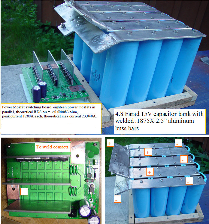
More internet searching turned up a guy that made his own dual pulse capacitor discharge welder. We passed a few e-mails back and forth, and I was able to buy one of his unpopulated Mosfet power switching PC boards for a reasonable price.
I ordered some components and built up the board. I was not able to find the power Mosfets that he used, so I got some that had even lower RDS on and higher current rating. Before trying the board, I decided that It was time to do the capacitor bank over again, with a more compact form factor, and aluminum buss bars instead of copper, as I was concerned about passing the high current across a dissimilar metal junction. I used 3/16 X 2.5" wide aluminum plate to make the buss bars, and tied them together with more 3/16 aluminum. To make the lowest resistance joints, I welded the joining buss bar to the main buss bars, around the periphery, and through 5 through holes on each bar. Should be ready to try it out in the next couple of days, as I have three MIMA systems to build first.
(Posted 5/15/2010 by mikey)
Making some cells for weld testing
freeing up the cells
Dan came over and we tried out the weld milling fixture.It worked well, but even at 120psi in the cylinders, the smooth steel battery against the garolite was slipping a bit when we were milling, so Dan put a strip of emery cloth in the jaws and the problem was solved. The weld spots needed to be smoothed out on the belt sander to remove any residual weld. The vice air switch was replaced by an air push button valve which was mounted on a bracket and nut that screws right into the quill feed lever, so you line up the weld, press the button with your thumb to lock the vice, pull down to mill the weld, retract the end mill and release the button rotate and repeat, It works pretty slick. The only improvement I can see is to automate the end mill coming down, so one would tap the button, and the vice would clamp,end mill come down to mill off the weld, end mill retracts and the vice would unlock. rotate the stick, hit it again.
(Posted 4/10/2010 by mikey)
More parts of the process
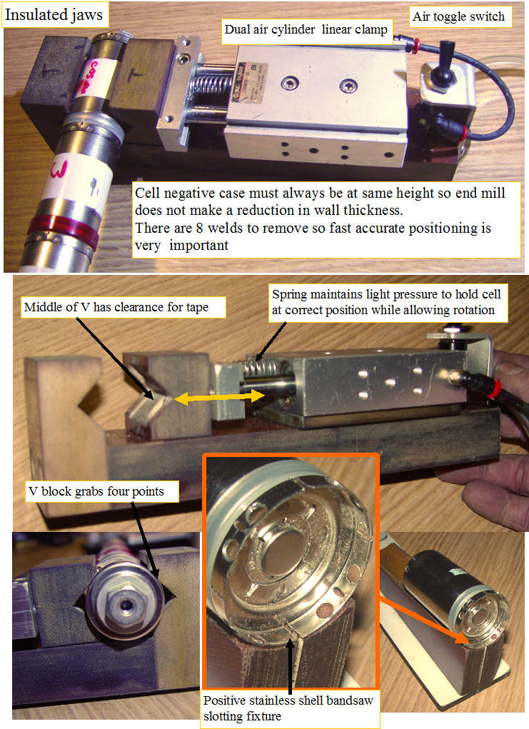
Milling and slotting fixtures
Ok I need to test the welder, but all I have is welded sticks. After spending 20 minutes separating cells on one stick, it became obvious that I needed a fixture to make that process go faster. I want enough loose cells to do some serious weld process tweaking,so 20 minutes per stick will not work for me. It is pretty important that when milling or sawing a live subpack that it remains electrically isolated form the machine, so I cut out some thick Garolite for the clamp/mill fixture. The V blocks assure repeatable clamped position so the end mill plunge depth can be set so the negative case is not milled, at any rotation position. The V blocks are held together gently by the spring, and with several hundred LBs of force when the air stage is activated for the milling. The clamp to unclamp happens in a fraction of a second. The fixture is held in the regular milling machine vice when in use.
The other tool required is the positive cup slotting fixture. It holds the stick or cell at the best angle for slotting the bottom edge while backing up the thin sheet metal with garolite so it cuts cleanly. The fixture fits on my bandsaw and holds the stick so it remains isolated electrically. The slot is required between the two spot welding tips, so the current flows down into the case and back out to the other welding post, rather than through the shorter path that would be present without the slot.
(Posted 4/8/2010 by mikey)
New weld head
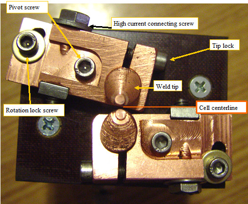
Weld head #2
Made a new weld head that can produce welds similar to what is used on the stock sticks. The system allows a relatively wide range of adjustments for width between welds and cell central axis. I also rebuilt the capacitor bank with the caps in series parallel configuration which will yield more energy with a higher operating voltage range of 0-30V. Will cut up some sticks and do a bunch of test welds. Initial test look very promising.
(Posted 4/5/2010 by mikey)
Spotwelding fixture #1
Spotwelder attempt #1
Found rugged linear stage with sufficient travel to cover all welds. Mounted heavy steel angle as table. Made phenolic cell supports. Made weld actuator and weld jaws. Test results: Not going to work reliability due to movable side contact not making good contact. The most positive battery electrode will not make contact with the movable electrode, so this fixture cannot do that weld. Will save these jaws for future reference and try a different approach.
(Posted 4/3/2010 by mikey)
More energy
Now we have some serious weld power
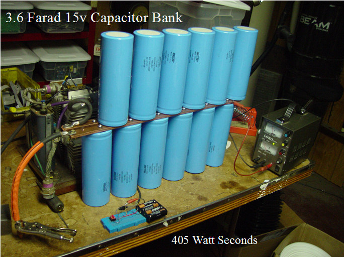
I made my trip to Boston and came home with sixteen 300,000uf 15V caps. The date code was 1984, but they were still in the shipping containers, and I charged each one to make sure they would charge to the 15V level. Brought them home, and before the car had cooled off, I had mounted 12 of them to my bus bars and gave them a few shots.The test welds look much better,the SCR did not have a problem with the energy, even at the full voltage I did not burn the metal, and the welds were nice and strong. The only problem with the concept is weld frequency. At 3A of recharge current, it takes half a minute to recharge the capacitor bank between shots. I will need an adjustable voltage 15-20A recharge supply to be able to weld a cell in a reasonable time.
Now I am ready to build the weld head.
(Posted 3/29/2010 by mikey)
First weld testing
crude but it works
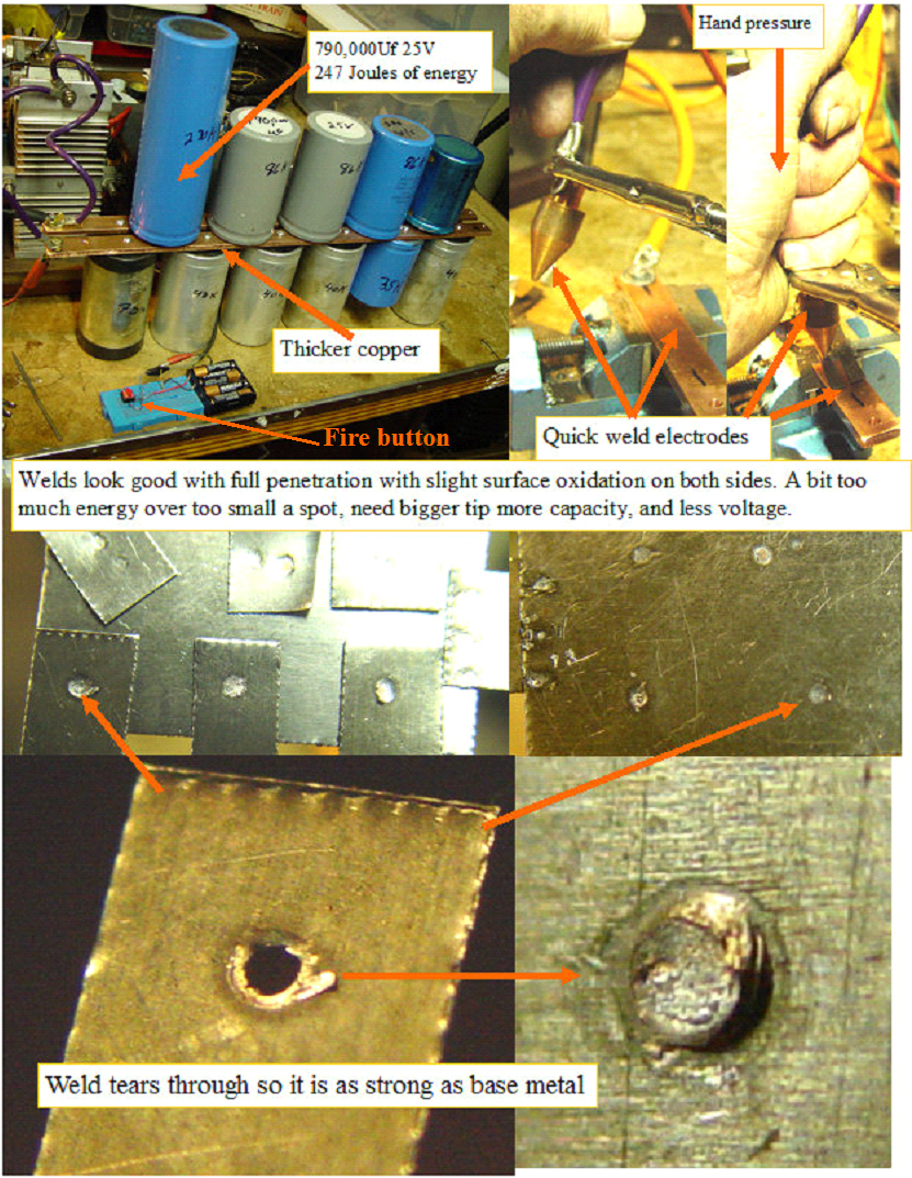
I rigged up some welding electrodes from copper bar and rod,made a fire button to manually turn on the big SCR,found some thin stainless sheet metal about the same thickness as the battery cases.
The first welds were not strong enough,and could be twisted off with only a tiny weld zone that was not sufficient, so I got some 1/4" X 1" copper bar to lower the resistance to the work and between the capacitors, dug out some more capacitors, and made a new capacitor bank. The new cap bank totaled 790,000Uf and can be charged to 25V, yielding 247 Joules or Watt seconds. The weld penetration looks complete across the electrode tip width, and is slightly burned, so we have more energy concentration than required, so a lower voltage or wider tip may work even better. The welds are quite strong, so we may have sufficient energy for welding the cells, but a bit more Capacitor, maybe a total of 1 Farad or so would be better. This would allow operation at lower voltages and will leave the base metal in better shape. Will put out some feelers to see if I can scrounge up some bigger Caps. Next I need to make the cell holding and weld electrode assembly and try welding real cells.
(Posted 3/25/2010 by mikey)
Making a spot welder??
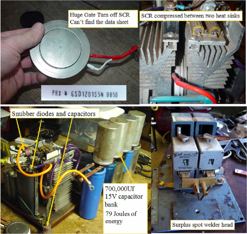
gathering components
There are several types of spot welders, but the best for spot welding batteries is the Capacitive Discharge welder. The advantages are repeatable energy delivery,and minimum heat effected zone. A nice production unit is about $6-12K with the weld head. Since I don't have that kind of money, I have to try building my own. I did some scrounging in my extensive junk pile, and came up with some possible components. I found 700,000 Uf of 15V or better capacitors. I mounted them so the lead length would be as short as possible, but did not have the 1"X 1/4" copper bus bars that I would have preferred to use, but the 1/2" X 1/4 that I had should be good enough for the prototype testing. I got the huge hockey puck SCR to work, and found that it is one of the rare GTO or Gate turnoff types, which means I could pulse the discharge without totally discharging the caps like a regular SCR would. I spoke with PowerX, but they could not find the part number so I really don't know much about the device except that it is huge, and that it worked when I tested it by firing a smaller cap into a resistor. I also dug up a small spot welding head. Not the components I would have bought for the machine, but hopefully it will be close enough to see some welds and get a starting point. The buss bars are too small, The caps are not big enough, and the weld head is kinda small