|
FAS install
|
 | |
|
FAS connections
|
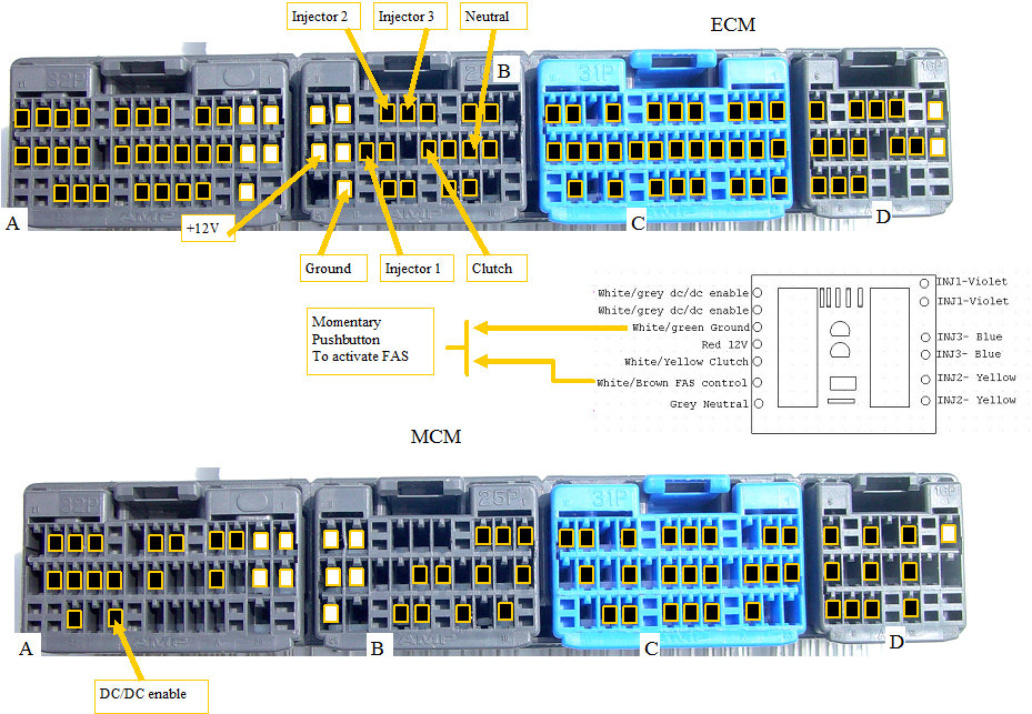
The install of the FAS when MIMA is not installed involves splicing into some wires at the ECM, running the DC/DC enable wires to the rear electronics area and splicing into the dc/dc wire there.
Follow the MIMA install instructions for accessing the ECM, and removing the rear covers.
gaining access
It is best that you unwrap the black tape and heavy plastic harness coverings at the ECM and MCM so you can have some slack in the wire for making your connections.
opening harness
The three injector wires from the ECM need to be cut, and the color coded FAS wires connected to both of the cut ends to complete the injector circuits.
The rest of the wires are just tapped onto the existing wires.
The FAS control wire (White/brown)is connected to a momentary push button switch (you supply), and the other side of the switch can go to chassis ground.
The DC/DC twisted pair from the FAS board is run to the rear electronics area through the e-brake enclosure, and up through the opening behind the seats.
You may want to fish a wire from the IMA area down to the e-brake as a fish that you can tie to the DC/DC wires, so you can pull them up into the rear area.
The DC/DC enable wire from the MCM connector A, is cut, and the FAS dc/dc wires connected one to each end of the cut wire.
All of the connections should be soldered and carefully taped. The cuts and splices should be made at least 3 inches from the rear of the connector so you can have some slack.
See the splicing instructions here.
splicing
The installed FAS board will tuck out of the way in the upper right ECM area.
As with any cutting and splicing job, take your time, and be careful that you are connecting to the correct wire,or the magic smoke will come out and that is a real bummer.
|
|
|