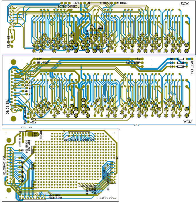
The Plug in adapter boards are here and are being built
|
 | |
|
The final boards finally
|
The final plug in boards are in hand.
Blue is top side, green is bottom side.
The ECM boards have pads to attach the FAS system.Three etch cuts at the fuel injector locations (oval silk screen)are required when FAS is attached. A single etch cut on the DC/DC enable line on the MCM board is required when FAS is used.The circles around a pad indicates that a pin wire must be attached. The thick circles indicate a large pin, thin is a small.
The ECM board has three extra conductors, E1,E2,E3, which can be used to bring any ECM signal to the distribution board. The Neutral,Clutch, Brake, and NEP(rpm) signals are included on the ribbon.
The MCM board has pads for seven spare conductors, M1 through M7, which can be used to bring MCM signals to the distribution board.
The distribution board ties everything together.
A breadboard area provides a place for expansion, both as a breadboard, or a place to mount a future interface board. The display 16 conductor ribbon connector can be plugged into the breadboard so other displays can be interfaced to that port. This expandable harness interface should provide all the future expansion that we will require to take the MIMA system to the next level, while making the system much simpler to install.
|
|