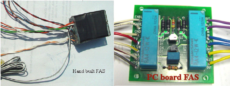
While MIMA and careful driving technique can yield some very impressive MPG,we have found that another simple modification can also boost the MPG even more. We call it the FAS mod. The Insight has a built in function called Autostop, which turns off the engine when you stop at a light. If you shift into neutral, clutch in, it can happen at up to 19 MPH. The Insight with electric power steering does not require the engine to be turning for power steering to work, and the vacuum boosted brakes have enough vacuum reserve to give several braking cycles. The engine is restarted automatically if you step on the accelerator, shift into gear, or the brake vacuum has dropped to a level where the vacuum boost does not have sufficient vacuum. All of these features make the car very safe during engine off coasting. An early MIMA user Calpod, was the first to tap into the fuel injector system with a momentary manually activated switch system that cut fuel to the engine by disconnecting the fuel injectors. A second switch simulated the clutch being pressed. This combination allowed him to cut the engine by temporarily starving it of fuel until it stalled, simulating autostop at any speed. Using this technique all of the safety systems for restarting the engine remained functioning, since the fuel cut was via a momentary switch. The down side of this system was that he had to switch the clutch sw manually, and the 12V charging system was disabled during the FAS cycle. Another MIMA user Highwater, further developed the FAS system by automating the clutch simulation switch with relays, and tied in the neutral switch to get the system back to normal operation when the gear shift was moved from the neutral position. Two wires were run to the rear IMA system to keep the 12V dc/dc charging system on while in the FAS cycle. Many Insight drivers were interested in this FAS system, so I offered a hand made FAS relay system. As part of the new MIMA build where I required some new PC boards, I turned the FAS system into a PC board with miniature PC board mounted relays. The FAS PC version is offered as part of the MIMA system as a $120 option, and will be wired to the ECM plug in adapter. Non MIMA FAS The FAS board is available as a separate item,which will work exactly the same as when in the MIMA system but instead of being inte3grated into the ECM plug in adapter,you will need to hardwired to the ECM harness. The control input, and two dc/dc enable wires will need to be extended so the dc/dc can run to the rear of the car. The FAS control wire can be extended to reach where you mount the FAS Normally Open momentary push button switch,the other terminal of the switch goes to chassis ground.
The separate FAS is $125 which includes postage and the extended DC/DC wires, with momentary switch.
What to expect after FAS install:
1. When the engine goes off with FAS, at speeds higher than 19 mph, the engine oil light comes on. That's normal. The oil light turns off when the engine comes back on.Use this as your FAS active indication.
2. To stop the engine with the momentary switch you have to hold the switch for a second or two. If the momentary contact is too short, the engine just rev's immediately back to up to idle speed.Hold it until you are sure the engine has stopped.
3. While the FAS operation simulates autostop with all the safety feachers it does not actually initiate a real autostop with the autostop light flashing etc. Enjoy!
FAS install
FAS connections
The install of the FAS when MIMA is not installed involves splicing into some wires at the ECM, running the DC/DC enable wires to the rear electronics area and splicing into the dc/dc wire there. Follow the MIMA install instructions for accessing the ECM, and removing the rear covers. gaining access
It is best that you unwrap the black tape and heavy plastic harness coverings at the ECM and MCM so you can have some slack in the wire for making your connections. opening harness
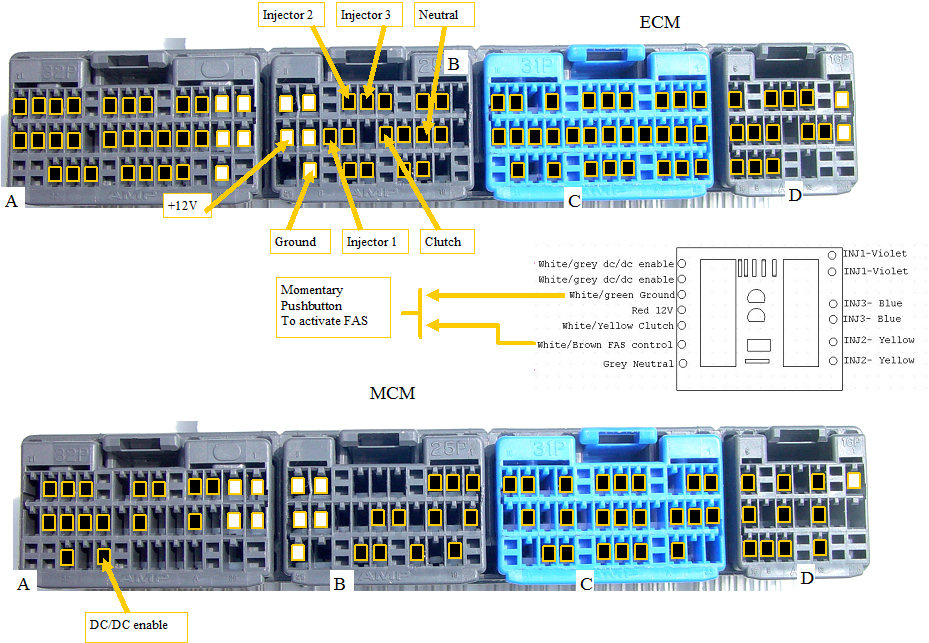
The three injector wires from the ECM need to be cut, and the color coded FAS wires connected to both of the cut ends to complete the injector circuits.
The rest of the wires are just tapped onto the existing wires.
The FAS control wire (White/brown)is connected to a momentary push button switch (you supply), and the other side of the switch can go to chassis ground.
The DC/DC twisted pair from the FAS board is run to the rear electronics area through the e-brake enclosure, and up through the opening behind the seats.
You may want to fish a wire from the IMA area down to the e-brake as a fish that you can tie to the DC/DC wires, so you can pull them up into the rear area.
The DC/DC enable wire from the MCM connector A, is cut, and the FAS dc/dc wires connected one to each end of the cut wire. All of the connections should be soldered and carefully taped. The cuts and splices should be made at least 3 inches from the rear of the connector so you can have some slack. See the splicing instructions here. splicing
The installed FAS board will tuck out of the way in the upper right ECM area. As with any cutting and splicing job, take your time, and be careful that you are connecting to the correct wire,or the magic smoke will come out and that is a real bummer.