Making a connector
|
 | |
|
Making the current sensor plug in adapter
|
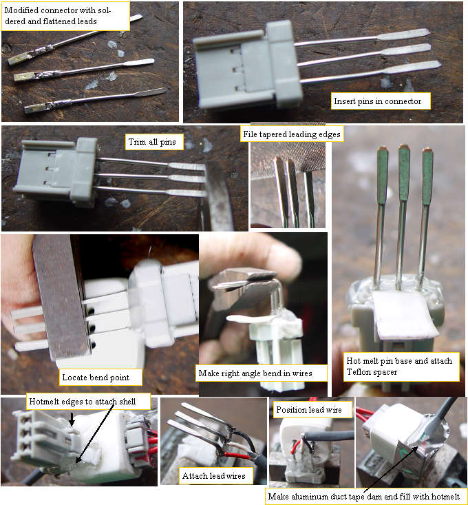
Like any multistep construction project,building the 3 pin right angle current sensor plug in adapter can be accomplished in many ways. The best procedure will be the one that gives the best results in the minimum amount of time.
After several connectors, I got it down to a simple process. The wires were all cut to the correct length+ 1/8 inch. They were crimped onto a receptacle then soldered, as a crimp onto solid wire will tend to loosen over time if not soldered. The receptacles need to be sanded to reshape them to fit correctly into the stock male plugs. The plugs also need to be modified. The pin ends are cut off so they are all the same length, then a tapered lead in is filed onto the end of each pin.The wires with receptacles are plugged into the plug, and the rear of the connector has some hot melt applied to seal the rear of the cavity, and to secure the teflon strip that stops the hotmelt from getting into the locking tab. The cast shell is used to determine exactly where to bend the leads for the right angle, then it is tacked at the corners with more hotmelt.
The three lead wires are soldered to the pins.
Finally a dam made of aluminum duct tape is carefully formed, and is filled with hotmelt to protect and secure the lead wires.A lot of work, but it is a nice secure connection and should not give us any problems.
To make sure we do not get any corrosion, the systems will include some protective connector jelly to protect the pins.
|
|
