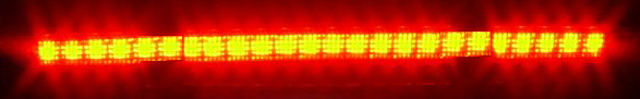
Using the high mounted led brake light as a regen indicator
|
 | |
|
Regen light
|
I have had a schematic on the downloads page for over a year that describes using the high mounted led brake light as a MIMA regen indicator.
schematic
Several people have asked for more detailed instructions on how and where to connect the relay, so I decided that I should install it on my silver insight, and describe the process.
The first thing required was to determine the amount of current that the LED's would require, so I made a direct measurement. The current is only 150MA, and the leds present a nice resistive load, so the relay requirements are very mild. The choice of relays is huge, and many of you will have a relay that would work in your spare component box. I sourced a new relay on Mousers website that is cheap, available, and has a reasonable coil current so the MIMA board does not have to control much power.
The Fujitsu MZ-12HG-K-U cost less than $3, and should be easy to work with.
The connection location that seems best to me is the blue connector under the passenger side B pillar bezel.
The Violet AUX1 wire in the earlier MIMA harness will be extended to reach the B pillar area where the relay will be mounted.
On the plug and play harness, just solder a wire to the Aux1 pad on the distribution board, and run it the same way.
It can be run under the passenger rug to the wiring area near the passenger door, and then into the B pillar area.
The blue 6 pin connector is where we will attach the relay.As you can see from the schematic, we will break the green/white wire that connects to pin 4 of the connector, and put the Normally Closed relay contacts (1-7) between the two ends of this wire.
The Normally Open contact(2)will splice into the Blue/yellow connector wire (13.6V) pin 5.
Pin 11 of the relay also connects to pin 5.
This relay is made for PC mounting, but you can solder the wires directly to the relay pins to make things easier.
The final wire is the MIMA AUX wire which connects to pin 12 of the relay. Whenever MIMA detects that more than 15A of regen are happening, it will turn on the LED brake light but not the regular brake lights.
To enable MIMA AUX1 for brake light, calibration option 4 needs to be on or not blinking.
An added feature may be to have 50% brightness when regen is the activation, and full brightness when the brakes are the activation. Simply add a resistor in series with the wire from the Blue/yellow tap for the 13.6V.I will determine the resistor size that works best when I get my system installed.
|
|
